In this tutorial we’ll explore various animated WebGL text typing effects. We will mostly be using Three.js but not the whole tutorial relies on the specific features of this library. But who doesn’t love Three.js though
This tutorial is aimed at developers who are familiar with the basic concepts of WebGL.
The main idea is to create a JavaScript template that takes a keyboard input and draws the text on the screen in some fancy way. The effects we will build today are all about composing a text shape with a big number of repeating objects. We will cover the following steps:
Sampling text on Canvas (generating 2D coordinates)
Setting up the scene and placing the Canvas element
Generating particles in 3D space
Turning particles to an instanced mesh
Replacing a static string with some user input
Basic animation
Typing-related animation
Generating the visuals: clouds, bubbles, flowers, eyeballs
Text sampling
In the following we will fill a text shape with some particles.
First, let’s think about what a 3D text shape is. In general, a text mesh is nothing but a 2D shape being extruded. So we don’t need to sample the 3rd coordinate – we can just use X/Y coordinates with Z being randomly generated within the text depth (although we’re not about to use the Z coordinate much today).
One of the ways to generate 2D coordinates inside the shape is with Canvas sampling. So let’s create a <canvas> element, apply some font-related styles to it and make sure the size of <canvas> is big enough for the text to fit (extra space is okay).
// Settings
const fontName = 'Verdana';
const textureFontSize = 100;

// String to show
let string = 'Some text' + '\n' + 'to sample' + '\n' + 'with Canvas';

// Create canvas to sample the text
const textCanvas = document.createElement('canvas');
const textCtx = textCanvas.getContext('2d');
document.body.appendChild(textCanvas);

// ---------------------------------------------------------------

sampleCoordinates();

// ---------------------------------------------------------------

function sampleCoordinates() {

    // Parse text
    const lines = string.split(`\n`);
    const linesMaxLength = [...lines].sort((a, b) => b.length - a.length)[0].length;
    const wTexture = textureFontSize * .7 * linesMaxLength;
    const hTexture = lines.length * textureFontSize;

    // ...
}
With the Canvas API you can set all the font styling pretty much like in CSS. Custom fonts can be used as well, but I’m using good old Verdana today.
Once the style is set, we draw the text (or any other graphics!) on the <canvas>…
function sampleCoordinates() {

    // Parse text
    // ...

    // Draw text
    const linesNumber = lines.length;
    textCanvas.width = wTexture;
    textCanvas.height = hTexture;
    textCtx.font = '100 ' + textureFontSize + 'px ' + fontName;
    textCtx.fillStyle = '#2a9d8f';
    textCtx.clearRect(0, 0, textCanvas.width, textCanvas.height);
    for (let i = 0; i < linesNumber; i++) {
        textCtx.fillText(lines[i], 0, (i + .8) * hTexture / linesNumber);
    }

    // ...
}
The ImageData object contains a one-dimensional array with RGBA data for every pixel. Knowing the size of the canvas, we can go through the array and check if the given X/Y coordinate matches the color of text or the color of the background.
Since our canvas doesn’t have anything but colored text on the unset (transparent black) background, we can check any of the four RGBA bytes with against a condition as simple as “bigger than zero”.
function sampleCoordinates() {
    // Parse text
    // ...
    // Draw text
    // ...
    // Sample coordinates
    textureCoordinates = [];
    const samplingStep = 4;
    if (wTexture > 0) {
        const imageData = textCtx.getImageData(0, 0, textCanvas.width, textCanvas.height);
        for (let i = 0; i < textCanvas.height; i += samplingStep) {
            for (let j = 0; j < textCanvas.width; j += samplingStep) {
                // Checking if R-channel is not zero since the background RGBA is (0,0,0,0)
                if (imageData.data[(j + i * textCanvas.width) * 4] > 0) {
                    textureCoordinates.push({
                        x: j,
                        y: i
                    })
                }
            }
        }
    }
}
There’re lots of things you can do with the sampling function: change the sampling step, add some randomness, apply an outline stroke to the text, and more. Below we’ll keep using only the simplest sampling. To check the result we can add a second <canvas> and draw the dot for each of sampled textureCoordinates.
It works
The Three.js scene
Let’s set up a basic Three.js scene and place a Plane object on it. We can use the text sampling Canvas from the previous step as a color map for the Plane.
Generating the particles
We can generate 3D coordinates with the very same sampling function. X/Y are gathered from the Canvas and for the Z coordinate we can take a random number.
The easiest way to visualize this set of coordinates would be a particle system known as THREE.Points.
function createParticles() {
    const geometry = new THREE.BufferGeometry();
    const material = new THREE.PointsMaterial({
        color: 0xff0000,
        size: 2
    });
    const vertices = [];
    for (let i = 0; i < textureCoordinates.length; i ++) {
        vertices.push(textureCoordinates[i].x, textureCoordinates[i].y, 5 * Math.random());
    }
    geometry.setAttribute('position', new THREE.Float32BufferAttribute(vertices, 3));
    const particles = new THREE.Points(geometry, material);
    scene.add(particles);
}
Somehow it works ¯\_(ツ)_/¯
Obviously, we need to flip the Y coordinate for each particle and center the whole text.
To do both, we need to know the bounding box of our text. There are various ways to measure the box using the canvas API or Three.js functions. But as a temporary solution, we just take max X and Y coordinates as width and height of the text.
function refreshText() {
    sampleCoordinates();

    // Gather with and height of the bounding box
    const maxX = textureCoordinates.map(v => v.x).sort((a, b) => (b - a))[0];
    const maxY = textureCoordinates.map(v => v.y).sort((a, b) => (b - a))[0];
    stringBox.wScene = maxX;
    stringBox.hScene = maxY;

    createParticles();
}
For each point, the Y coordinate becomes boxTotalHeight - Y.
Shifting the whole particles system by half-width and half-height of the box solves the centering issue.
function createParticles() {

    // ...
    for (let i = 0; i < textureCoordinates.length; i ++) {
       // Turning Y coordinate to stringBox.hScene - Y
       vertices.push(textureCoordinates[i].x, stringBox.hScene - textureCoordinates[i].y, 5 * Math.random());
    }
    // ...

    // Centralizing the text
    particles.position.x = -.5 * stringBox.wScene;
    particles.position.y = -.5 * stringBox.hScene;
}
Until now, we were using pixel coordinates gathered from text canvas directly on the 3D scene. But let’s say we need the 3D text to have the height equal to 10 units. If we set 10 as a font size, the canvas resolution would be too low to make a proper sampling. To avoid it (and to be more flexible with the particles density), we can add an additional scaling factor: the value we’d multiply the canvas coordinates with before using them in 3D space.
At this point, we can also remove the Plane object. We keep using the canvas to draw the text and sample coordinates but we don’t need to turn it to a texture and put it on the scene.
Switching to instanced mesh
Of course there are many cool things we can do with THREE.Points but our next step is turning the particles into THREE.InstancedMesh.
The main limitation of THREE.Points is the particle size. THREE.PointsMaterial is based on WebGL gl_PointSize, which can be rendered with a maximum pixel size of around 50 to 100, depending on your video card. So even if we need our particles to be as simple as planes, we sometimes can’t use THREE.Points due to this limitation. You may think about THREE.Sprite as an alternative, but (surprisingly) instanced mesh gives us much better performance on the big (10k+) number of particles.
Plus, if we want to use 3D shapes as particles, THREE.InstancedMesh is the only choice.
There is a well-known approach to work with THREE.InstancedMesh:
Create an instanced mesh with a known number of instances. In our case, the number of instances is the length of our coordinates array.
function createInstancedMesh() {
    instancedMesh = new THREE.InstancedMesh(particleGeometry, particleMaterial, textureCoordinates.length);
    scene.add(instancedMesh);

    // centralize it in the same way as before
    instancedMesh.position.x = -.5 * stringBox.wScene;
    instancedMesh.position.y = -.5 * stringBox.hScene;
}
Add the geometry and material to be used for each instance. I use a doughnut shape known as THREE.TorusGeometry and THREE.MeshNormalMaterial.
function init() {
    // Create scene and text canvas
    // ...

    // Instanced geometry and material
    particleGeometry = new THREE.TorusGeometry(.1, .05, 16, 50);
    particleMaterial = new THREE.MeshNormalMaterial({ });

    // ...
}
Create a dummy object that helps us generate a 4×4 transform matrix for each particle. It doesn’t need to be a part of the scene.
function init() {
    // Create scene, text canvas, instanced geometry and material
    // ...

    dummy = new THREE.Object3D();
}
Apply the transform matrix to each instance with the .setMatrixAt method
function updateParticlesMatrices() {
    let idx = 0;
    textureCoordinates.forEach(p => {

        // we apply samples coordinates like before + some random rotation
        dummy.rotation.set(2 * Math.random(), 2 * Math.random(), 2 * Math.random());
        dummy.position.set(p.x, stringBox.hScene - p.y, Math.random());

        dummy.updateMatrix();
        instancedMesh.setMatrixAt(idx, dummy.matrix);

        idx ++;
    })
    instancedMesh.instanceMatrix.needsUpdate = true;
}
Listening to the keyboard
So far, the string value was hard-coded. We want it to be dynamic and contain the user input.
There are many ways to listen to the keyboard: working directly with keyup/keydown events, using the HTML input element as a proxy, etc. I ended up with a <div> element that has a contenteditable attribute set. Compared to an <input> or a <textarea>, it’s more painful to parse the multi-line string from an editable <div>. But it’s much easier to get an accurate pixel values for the cursor position and the text bounding box.
I won’t go too much into details here. The main idea is to keep the editable <div> focused all the time so that we keep track of whatever the user types there.
Using the keyup event we parse the string and get the width and height of stringBox from the contenteditable <div>, and then refresh the instanced mesh.
While parsing, we replace the inner tags with new lines (this part is specific for <div contenteditable>), and do a few things for usability like disabling empty new lines above and below the text.
Please note that <div contenteditable> and text canvas should have the same CSS properties (font, font size, etc). With the same styles applied, the text is rendered in the very same way on both elements. With that in place, we can take the pixel values from <div contenteditable> (text width, height, cursor position) and use them for the canvas.
Once we have the string and the stringBox, we update the instanced mesh.
function refreshText() {
    sampleCoordinates();
    textureCoordinates = textureCoordinates.map(c => {
        return { x: c.x * fontScaleFactor, y: c.y * fontScaleFactor }
    });
    // This part can be removed as we take text size from editable <div>
    // const sortedX = textureCoordinates.map(v => v.x).sort((a, b) => (b - a))[0];
    // const sortedY = textureCoordinates.map(v => v.y).sort((a, b) => (b - a))[0];
    // stringBox.wScene = sortedX;
    // stringBox.hScene = sortedY;</s>
    recreateInstancedMesh();
    updateParticlesMatrices();
}
Coordinate sampling is the same as before with one difference: we now can create canvas with the exact text size, no extra space to sample.
function sampleCoordinates() {
    const lines = string.split(`\n`);
    // This part can be removed as we take text size from editable <div>
    // const linesMaxLength = [...lines].sort((a, b) => b.length - a.length)[0].length;
    // stringBox.wTexture = textureFontSize * .7 * linesMaxLength;
    // stringBox.hTexture = lines.length * textureFontSize;
    textCanvas.width = stringBox.wTexture;
    textCanvas.height = stringBox.hTexture;
    // ...
}
We can’t increase the number of instances for the existing mesh. So the mesh should be recreated every time the text is updated. Although text centering and instances transform is done exactly like before.
// function createInstancedMesh() {
function recreateInstancedMesh() {

    // Now we need to remove the old Mesh and create a new one every refreshText() call
    scene.remove(instancedMesh);
    instancedMesh = new THREE.InstancedMesh(particleGeometry, particleMaterial, textureCoordinates.length);

    // ...
}

function updateParticlesMatrices() {

    // same as before
    //...

}
Since our text is dynamic and it can get pretty long, let’s make sure the instanced mesh fits the screen:
One more thing to add is a caret (text cursor). It can be a simple 3D box with a size matching the font size.
function init() {
    // ...
    const cursorGeometry = new THREE.BoxGeometry(.3, 4.5, .03);
    cursorGeometry.translate(.5, -2.7, 0)
    const cursorMaterial = new THREE.MeshNormalMaterial({
        transparent: true,
    });
    cursorMesh = new THREE.Mesh(cursorGeometry, cursorMaterial);
    scene.add(cursorMesh);
}
We gather the position of the caret from our editable <div> in pixels and multiply it by fontScaleFactor, like we do with the bounding box width and height.
function handleInput() {

    // ...

    stringBox.caretPosScene = getCaretCoordinates().map(c => c * fontScaleFactor);

    function getCaretCoordinates() {
        const range = window.getSelection().getRangeAt(0);
        const needsToWorkAroundNewlineBug = (range.startContainer.nodeName.toLowerCase() === 'div' && range.startOffset === 0);
        if (needsToWorkAroundNewlineBug) {
            return [
                range.startContainer.offsetLeft,
                range.startContainer.offsetTop
            ]
        } else {
            const rects = range.getClientRects();
            if (rects[0]) {
                return [rects[0].left, rects[0].top]
            } else {
                // since getClientRects() gets buggy in FF
                document.execCommand('selectAll', false, null);
                return [
                    0, 0
                ]
            }
        }
    }
}
The cursor just needs same centering as our instanced mesh has, and voilà, the 3D caret position is the same as in the the input div.
The only thing left is to make the cursor blink when the page (and hence the input element) is focused. The roundPulse function generates the rounded pulse between 0 and 1 from THREE.Clock.getElapsedTime(). We need to update the cursor opacity all the time, so the updateCursorOpacity call goes to the main render loop.
Instead of setting the instances transform just on the text update, we can also animate this transform.
To do this, we add an additional array of Particle objects to store the parameters for each instance. We still need the textureCoordinates array to store the 2D coordinates in pixels, but now we remap them to the particles array. And obviously, the particles transform update should happen in the main render loop now.
// ...
let textureCoordinates = [];
let particles = [];

function refreshText() {

    // ...

    // textureCoordinates are only pixel coordinates, particles is array of data objects
    particles = textureCoordinates.map(c =>
        new Particle([c.x * fontScaleFactor, c.y * fontScaleFactor])
    );

    // We call it in the render() loop now
    // updateParticlesMatrices();

    // ...
}
Each Particle object contains a list of properties and a grow() function that updates some of those properties.
For starters, we define position, rotation and scale. Position would be static for each particle, scale would increase from zero to one when the particle is created, and rotation would be animated all the time.
We already have a nice template by now. But every time the text is updated we recreate all the instances for all the symbols. So every time the text is changed we reset all the properties and animations of all the particles.
Instead, we need to keep the properties and animations for “old” particles. To do so, we need to know if each particle should be recreated or not.
In other words, for each sampled coordinate we need to check if Particle already exists or not. If we found a Particle object with the same X/Y coordinates, we keep it along with all its properties. If there is no existing Particle for the sampled coordinate, we call new Particle() like we did before.
We evolve the sampling function so we don’t only gather the X/Y values and refill textureCoordinates array but also do the following:
Turn one-dimensional array imageData to two-dimensional imageMask array
Go through the existing textureCoordinates array and compare its elements to the imageMask. If coordinate exists, add old property to the coordinate, otherwise add toDelete property.
All the sampled coordinates that were not found in the textureCoordinates, we handle as new coordinate that has X and Y values and old or toDelete properties set to false
It would make sense to simply delete old coordinates that were not found in the new imageMask. But we use a special toDelete property instead to play a fade-out animation for deleted particles first, and actually delete the Particle data only in the next step.
function sampleCoordinates() {
    // Draw text
    // ...
    // Sample coordinates
    if (stringBox.wTexture > 0) {
        // Image data to 2d array
        const imageData = textCtx.getImageData(0, 0, textCanvas.width, textCanvas.height);
        const imageMask = Array.from(Array(textCanvas.height), () => new Array(textCanvas.width));
        for (let i = 0; i < textCanvas.height; i++) {
            for (let j = 0; j < textCanvas.width; j++) {
                imageMask[i][j] = imageData.data[(j + i * textCanvas.width) * 4] > 0;
            }
        }
        if (textureCoordinates.length !== 0) {
            // Clean up: delete coordinates and particles which disappeared on the prev step
            // We need to keep same indexes for coordinates and particles to reuse old particles properly
            textureCoordinates = textureCoordinates.filter(c => !c.toDelete);
            particles = particles.filter(c => !c.toDelete);
            // Go through existing coordinates (old to keep, toDelete for fade-out animation)
            textureCoordinates.forEach(c => {
                if (imageMask[c.y]) {
                    if (imageMask[c.y][c.x]) {
                        c.old = true;
                        if (!c.toDelete) {
                            imageMask[c.y][c.x] = false;
                        }
                    } else {
                        c.toDelete = true;
                    }
                } else {
                    c.toDelete = true;
                }
            });
        }
        // Add new coordinates
        for (let i = 0; i < textCanvas.height; i++) {
            for (let j = 0; j < textCanvas.width; j++) {
                if (imageMask[i][j]) {
                    textureCoordinates.push({
                        x: j,
                        y: i,
                        old: false,
                        toDelete: false
                    })
                }
            }
        }
    } else {
        textureCoordinates = [];
    }
}
With old and toDelete properties, mapping texture coordinates to the particles becomes conditional:
function refreshText() {

    // ...

    // particles = textureCoordinates.map(c =>
    //     new Particle([c.x * fontScaleFactor, c.y * fontScaleFactor])
    // );
    particles = textureCoordinates.map((c, cIdx) => {
        const x = c.x * fontScaleFactor;
        const y = c.y * fontScaleFactor;
        let p = (c.old && particles[cIdx]) ? particles[cIdx] : new Particle([x, y]);
        if (c.toDelete) {
            p.toDelete = true;
            p.scale = 1;
        }
        return p;
    });

    // ...

}
The grow() call would not only increase the size of the particle when it’s created. We would also decrease it if the particle meant to be deleted.
function Particle([x, y]) {
    // ...

    this.toDelete = false;

    this.grow = function () {
        // ...
        if (this.scale < 1) {
            this.scale += this.deltaScale;
        }
        if (this.toDelete) {
            this.scale -= this.deltaScale;
            if (this.scale <= 0) {
                this.scale = 0;
            }
        }
    }
}
The template is now ready and we can use it to create various effects with only little changes.
Here is the full list of changes I made to make these bubbles based on the template:
Change TorusGeometry to IcosahedronGeometry so each instance is a sphere
Replace MeshNormalMaterial with ShaderMaterial. You can check out the GLSL code in the sandbox above but the shader essentially does this:
mix white color and randomized gradient (taken from normal vector), and use the result as sphere color
applies transparency in a way to make less transparent outline and more transparent middle of the sphere if you look from the camera position
Adjust textureFontSize and fontScaleFactor values to change the density of the particles
Evolve the Particle object so that
bubble position is a bit randomized comparing to the sampled coordinates
maximum size of the bubble is defined by randomized maxScale property
no rotation
bubbles size is randomized as the scale limit is maxScale property, not 1
bubble grows all the time, bursts, and then grows again. So the scale increase happens not only when Particle is created but all the time. Once the scale reaches the maxScale value, we reset the scale to zero
some bubbles would get isFlying property so they move up from the initial position
Change color of page background and cursor
Clouds effect
You don’t need to do much for having clouds, too:
Use PlaneGeometry for instance shape
Use MeshBasicMaterial and apply the following image as an alpha map
Adjust textureFontSize and fontScaleFactor to change the density of the particles
Evolve the Particle object so that
particle position is a bit randomized compared to the sampled coordinates
size of the particle is defined by randomized maxScale property
only rotation around Z axis is needed
particle size (scale) is pulsating all the time
Additional transform dummy.quaternion.copy(camera.quaternion) should be applied for each instance. This way the particle is always facing towards the camera; rotate the cloudy text to see the result
Flowers are actually quite similar to clouds. The main difference is about having two instanced meshes and two materials. One is mapped as flower texture, another one as a leaf
Also, all the particles must have a new color property. We apply colors to the instanced mesh with the setColorAt method every time we recreate the meshes.
With a few small changes like particles density, scaling speed, rotation speed, and the color of the background and cursor, we have this:
We can go further and load a glb model and use it as an instance! I took this nice looking eye from turbosquid.com
Instead of applying a random rotation, we can make the eyeballs follow the mouse position! To do so, we need an additional transparent plane in front of the instanced mesh, THREE.Raycaster() and the mouse position tracker. We are listening to the mousemove event, set ray from mouse to the plane, and make the dummy object look at the intersection point.
Don’t forget to add some lights to see the imported model. And as we have lights, let’s make the instanced mesh cast the shadow to the plane behind the text.
Together with some other small changes like sampling density, grow() function parameters, cursor and background style, we get this:
In this tutorial you’ll learn how to create an interesting looking audio visualizer that also takes input from the web camera. The result is a creative visualizer with a depth distortion effect. Although the final result looks complex, the Three.js code that powers it is straightforward and easy to understand.
So let’s get started.
Processing flow
The processing flow of our script is going to be the following:
Create a vertex from every pixel of the image we get from the web camera input
Use the image data from the web camera and apply the magnitude value of the sound frequency to the Z coordinate of each particle
Draw
Repeat point 2 and 3
Now, let’s have a look at how we can get and use the data from the web camera.
Web camera
First of all, let’s see how to access the web camera and get an image from it.
Camera access
For camera access in the browser, simply use getUserMedia().
video = document.getElementById("video");

const option = {
    video: true,
    audio: false
};

// Get image from camera
navigator.getUserMedia(option, (stream) => {
    video.srcObject = stream;  // Load as source of video tag
    video.addEventListener("loadeddata", () => {
        // ready
    });
}, (error) => {
    console.log(error);
});
Draw camera image to canvas
After camera access succeeded, we’ll get the image from the camera and draw it on the canvas.
const getImageDataFromVideo = () => {
    const w = video.videoWidth;
    const h = video.videoHeight;

    canvas.width = w;
    canvas.height = h;

    // Reverse image like a mirror
    ctx.translate(w, 0);
    ctx.scale(-1, 1);

    // Draw to canvas
    ctx.drawImage(image, 0, 0);

    // Get image as array
    return ctx.getImageData(0, 0, w, h);
};
About acquired imageData
ctx.getImageData() returns an array which RGBA is in order.
[0]  // R
[1]  // G
[2]  // B
[3]  // A

[4]  // R
[5]  // G
[6]  // B
[7]  // A...
And this is how you can access the color information of every pixel.
for (let i = 0, len = imageData.data.length; i < len; i+=4) {
    const index = i * 4;  // Get index of "R" so that we could access to index with 1 set of RGBA in every iteration.?0, 4, 8, 12...?
    const r = imageData.data[index];
    const g = imageData.data[index + 1];
    const b = imageData.data[index + 2];
    const a = imageData.data[index + 3];
}
Accessing image pixels
We are going to calculate the X and Y coordinates so that the image can be placed in the center.
const imageData = getImageDataFromVideo();
for (let y = 0, height = imageData.height; y < height; y += 1) {
    for (let x = 0, width = imageData.width; x < width; x += 1) {
        const vX = x - imageData.width / 2;  // Shift in X direction since origin is center of screen
        const vY = -y + imageData.height / 2;  // Shift in Y direction in the same way (you need -y)
    }
}
Create particles from image pixels
For creating a particle, we can use THREE.Geometry() and THREE.PointsMaterial().
Each pixel is added to the geometry as a vertex.
const geometry = new THREE.Geometry();
geometry.morphAttributes = {};
const material = new THREE.PointsMaterial({
    size: 1,
    color: 0xff0000,
    sizeAttenuation: false
});

const imageData = getImageDataFromVideo();
for (let y = 0, height = imageData.height; y < height; y += 1) {
    for (let x = 0, width = imageData.width; x < width; x += 1) {
        const vertex = new THREE.Vector3(
            x - imageData.width / 2,
            -y + imageData.height / 2,
            0
        );
        geometry.vertices.push(vertex);
    }
}
particles = new THREE.Points(geometry, material);
scene.add(particles);
Draw
In the drawing stage, the updated image is drawn using particles by getting the image data from the camera and calculating a grayscale value from it.
By calling this process on every frame, the screen visual is updated just like a video.
const imageData = getImageDataFromVideo();
for (let i = 0, length = particles.geometry.vertices.length; i < length; i++) {
    const particle = particles.geometry.vertices[i];
    let index = i * 4;

    // Take an average of RGB and make it a gray value.
    let gray = (imageData.data[index] + imageData.data[index + 1] + imageData.data[index + 2]) / 3;

    let threshold = 200;
    if (gray < threshold) {
        // Apply the value to Z coordinate if the value of the target pixel is less than threshold.
        particle.z = gray * 50;
    } else {
        // If the value is greater than threshold, make it big value.
        particle.z = 10000;
    }
}
particles.geometry.verticesNeedUpdate = true;
Audio
In this section, let’s have a look at how the audio is processed.
Loading of the audio file and playback
For audio loading, we can use THREE.AudioLoader().
For getting the average frequency analyser.getAverageFrequency() comes in handy.
By applying this value to the Z coordinate of our particles, the depth effect of the visualizer is created.
Getting the audio frequency
And this is how we get the audio frequency:
// About fftSize https://developer.mozilla.org/en-US/docs/Web/API/AnalyserNode/fftSize
analyser = new THREE.AudioAnalyser(audio, fftSize);

// analyser.getFrequencyData() returns array of half size of fftSize.
// ex. if fftSize = 2048, array size will be 1024.
// data includes magnitude of low ~ high frequency.
const data = analyser.getFrequencyData();

for (let i = 0, len = data.length; i < len; i++) {
    // access to magnitude of each frequency with data[i].
}
Combining web camera input and audio
Finally, let’s see how the drawing process works that uses both, the camera image and the audio data.
Manipulate the image by reacting to the audio
By combining the techniques we’ve seen so far, we can now draw an image of the web camera with particles and manipulate the visual using audio data.
const draw = () => {
    // Audio
    const data = analyser.getFrequencyData();
    let averageFreq = analyser.getAverageFrequency();

    // Video
    const imageData = getImageData();
    for (let i = 0, length = particles.geometry.vertices.length; i < length; i++) {
        const particle = particles.geometry.vertices[i];

        let index = i * 4;
        let gray = (imageData.data[index] + imageData.data[index + 1] + imageData.data[index + 2]) / 3;
        let threshold = 200;
        if (gray < threshold) {
            // Apply gray value of every pixels of web camera image and average value of frequency to Z coordinate of particle.
            particle.z = gray * (averageFreq / 255);
        } else {
            particle.z = 10000;
        }
    }
    particles.geometry.verticesNeedUpdate = true;  // Necessary to update

    renderer.render(scene, camera);

    requestAnimationFrame(draw);
};
And that’s all. Wasn’t that complicated, was it? Now you know how to create your own audio visualizer using web camera and audio input.
We’ve used THREE.Geometry and THREE.PointsMaterial here but you can take it further and use Shaders. Demo 2 shows an example of that.
We hope you enjoyed this tutorial and get inspired to create something with it.
A good understanding of SVG is a rare skill. Surprisingly often, SVG is treated as just another image format. We use SVG because of its scalability and smaller file size, but in reality, SVG is so much more!
In this article, I’ll shed light on three of the most popular design tools: Adobe Illustrator, Sketch, and Figma. There are also other tools available supporting SVG that may have other functionalities and implement other solutions.
Note: If not stated otherwise, the content of this article is referring to SVG 1.1 2nd Edition. Some of the points discussed below would not apply to SVG 2, however, it still hasn’t reached the recommendation status, leaving SVG 1.1 as the most up-to-date specification.
Why Bother About Design Tools?
SVG is an XML-based markup language and, like any other programming language, can be written and edited in a text editor. So theoretically, as opposed to JPG or PNG files, we don’t need any GUI software to create SVG. However, in a vast majority of cases, using graphic design applications is inevitable.
Working with complicated shapes and graphics in a text-based format is utterly possible, but usually would be very tricky and tedious. Therefore, it’s common practice to use applications such as Adobe Illustrator, Sketch or Figma to design graphics visually, and then export them to an SVG format.
So no matter if you’re a designer that codes or a design-conscious developer, a good proficiency in working with SVG requires a bit of knowledge from both sides: design tools and the SVG language itself. To better understand the relation between the two, let’s take a closer look at what graphic design apps have to offer and how their features translate to SVG.
Basic Shapes
Many vector graphics are build out of a few basic shapes — grouped, transformed and combined with each other. The table below represents what shape tools are available in Illustrator, Sketch, and Figma and what SVG elements they are exported as.
Illustrator
Sketch
Figma
Generated SVG
Ellipse Tool
Oval
Ellipse
<circle /> or <ellipse />
Rectangle Tool
Rectangle
Rectangle
<rect />
Rounded Rectangle Tool
Rounded
-
<rect rx="…" />
Line Segment Tool
Line
Line
<line /> (Illustrator and Figma) <path /> (Sketch)
-
Arrow
Arrow
<path />
Polygon Tool
Polygon
Polygon
<polygon /> (Illustrator and Sketch) <path /> (Figma)
Star Tool
Star
Star
<polygon /> (Illustrator and Sketch) <path /> (Figma)
-
Triangle
-
<polygon />
Ellipses And Circles
One of the basic shapes in every design tool is an ellipse. In SVG, we will find a matching <ellipse /> element, defined by the coordinates of the ellipse’s centre (cx and cy) and two radii (rx and ry).
The very special type of ellipse is a circle. A circle is an ellipse with rx and ry radii equal to each other. SVG has its own <circle /> element that takes one attribute less as there’s only one radius to be taken into account:
In case of ellipses and circles, all design tools work the same: Ellipse Tool in Illustrator, Oval tool in Sketch and Ellipse tool in Figma will all generate <ellipse /> element unless the radii are equal: in such cases we will end up with a <circle /> element.
Rectangles And Rounded Rectangles
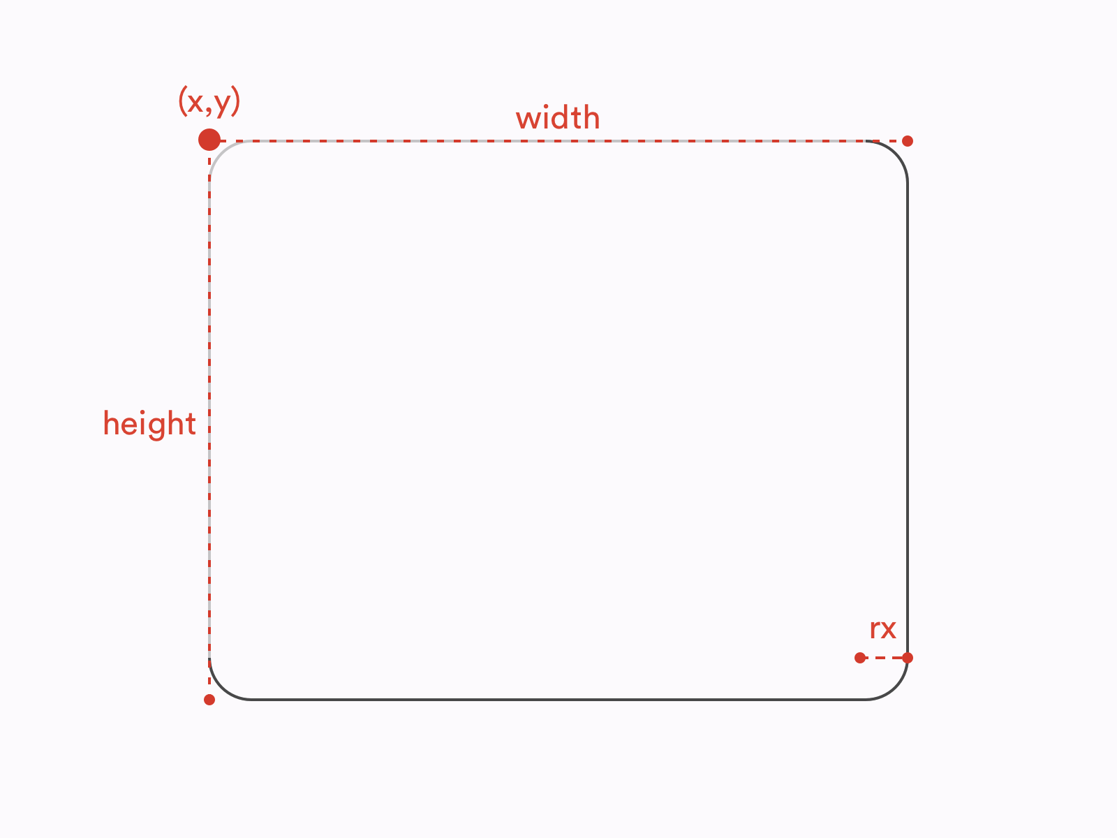
Another basic shape common to all design tools is a rectangle. In case of all design tools, using a rectangle tool generates a <rect /> element in SVG. A basic <rect /> is defined by 4 attributes: its x and y coordinates, along with its width and height:
Notice that while <ellipse />’s and <circle />’s position is defined by their geometrical centers, the position of a <rect /> is defined by the coordinates of its top left corner.
Apart from basic rectangles, we often use rectangles with rounded corners. In all three design tools, you can turn a rectangle into a rounded rectangle by applying a border radius to it in the Inspector or the Properties panel.
Additionally, in Sketch and Illustrator, there are tools dedicated to creating rounded rectangles (Rounded Rectangle Tool in Illustrator and Rounded tool in Sketch). However, there’s no difference between a regular rectangle with a radius applied and a rounded rectangle drawn with a Rounded Rectangle tool.
Therefore, no matter how created, a rounded rectangle will be exported using the following syntax:
One significant difference between design tools and SVG is how radii are defined. In all the design tools we consider, border radius is defined by a single variable. We can think of border radii as little circles used to mask the corners of our rectangles:
Meanwhile, in SVG border radii can be defined by two attributes: rx (as in the example above) and ry. They allow us to create rectangles with elliptical corners. You can think of such rounded corners as ellipses used as masks instead of circles:
So, in this case, SVG offers you more possibilities than design tools.
Note: Even though it’s not exactly related to the topic of this article, it’s worth noting that the difference described above applies to both SVG and HTML/CSS. The CSS propertyborder-radiusthat is used to style nodes such as divs and spans also allows creating elliptical corners. You can see an example below.
border-radius: 10px 5% / 20px 25em 30px 35em;
Values before the slash (/) are horizontal radii (equivalent of rx) and values after the slash are vertical values (equivalent of ry).
Rounded Rectangles With Multiple Radii
In design tools, the same as in CSS, each of the corners of a rectangle can be controlled separately. In other words, each corner can have its own radius (or no radius altogether). Such operation is not possible on a <rect /> element in SVG. Each <rect /> element has only one rx and one ry attribute. If you create a rectangle with multiple radii applied to its corners, the design tool will generate a <path /> element instead of a <rect /> element. We will talk more of a <path /> element in the next section.
Smooth Corners
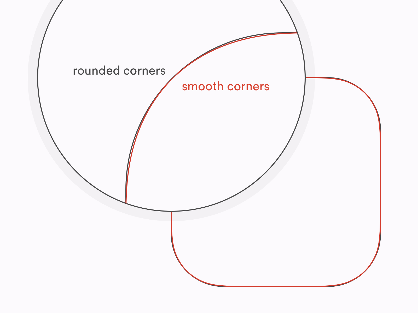
One of the interesting features introduced by Sketch and Figma not that long ago is smooth corners. In short, smooth corners use an irregular border-radius to achieve a result that looks more natural and, well, smooth. The most common application of smooth corners is app icons and other rounded elements on iOS. Apple used “regular” rounded corners on its mobile platform until iOS6 and then switched to what we call today “smooth” corners as a part of the big redesign introduced in 2013 (iOS7).
Difference between rounded and smooth corners (Large preview)
In Sketch, you can achieve smooth corners effect by switching between Round Corners and Smooth Corners in Inspector. Figma is giving you even more control over your corners as you can manipulate with the level of smoothness in the Corner Smoothing menu.
Unfortunately, none of these can be easily translated to SVG as SVG doesn’t know the concept of smooth corners at all. There’s also an important difference between what Sketch and Figma do if you try to export a rectangle with smooth corners to SVG.
Figma ignores the smooth corners, and exports a rectangle as a regular <rect /> element with rounded corners. Sketch, on the other hand, exports a rectangle with smooth corners as a <path /> that is trying to replicate the true shape of smooth corners. So Figma gives us worse accuracy for the sake of keeping a rectangle a rectangle, while Sketch is aiming at maximum possible accuracy at the cost of semantics and bigger file size. If you’d like to understand better what does this difference mean, we will dig deeper into the pros and cons of preserving basic shapes a bit later.
Lines
The next basic type of element is a line. In this case, we refer to a line as a single straight line going from point A to point B.
Illustrator, Sketch and Figma all offer their own line tools dedicated to drawing lines.
In SVG, we have a <line /> element. Four of its attributes are required: the coordinates of its starting point and the coordinates of its end point:
When it comes to exporting, Illustrator and Figma will export lines as <line /> elements where possible, while Sketch will always compute lines to <path /> elements.
Polylines
Now let’s take a look at polylines. Polyline is a connected series of straight lines. Polylines don’t have dedicated tools in the design tools. They can be drawn with a Pen tool (in Illustrator and Figma) or with a Vector tool (in Sketch).
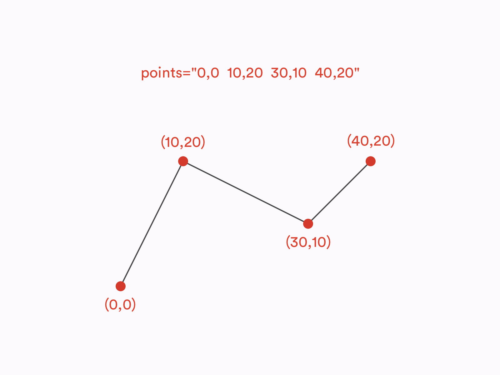
In, SVG, polylines are defined with a <polyline /> element. <polyline /> is drawn using a points attribute which is a list of coordinates defining all the points that create a polyline. Let’s take a look at an example of a polyline made out of three segments and four points:
Illustrator and Sketch translate polylines to <polyline/> elements, whilst Figma exports polylines as <path />s.
Arrows
In all three tools, you can control the ends of the lines to turn them into arrows and such. And all three tools will export such lines as <path />s, even if without the caps applied the same shapes would be translated to <line />s or <polyline />s. Is it because SVG doesn’t support arrows? Not exactly.
Actually, SVG specification does include customizable line ends which are known as markers. However, none of the design tools we mentioned use markers in the SVG they generate.
<marker> is a separate SVG element that can be defined within SVG’s <defs> and then used on <line>, <polyline> and <path> elements with marker attributes: marker, marker-start, marker-mid and marker-end. If you’d like to learn more about these attributes, I would recommend you to check out the official W3C documentation.
Polygons And Stars
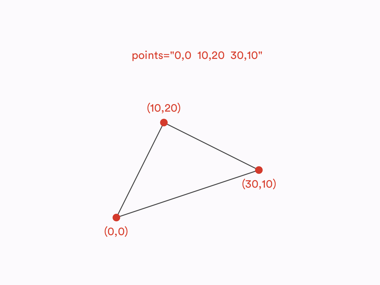
The last basic shape we’ll take a look at it is a polygon. Polygon is a closed shape made of straight lines, e.g. star or a hexagon. You can also think of it as of a closed polyline. The syntax of a <polygon /> element in SVG is actually the same as of a <polyline />. The only difference between the two is that in the <polygon /> the last point on the list is always being connected with the first point to make a <polygon /> a closed shape.
Some polygons are regular polygons. What is special about regular polygons is that all of their sides and angles are equal. To draw regular polygons, such as a hexagon or a pentagon, you can use a Polygon tool, same in Illustrator, Sketch and Figma. Polygon tools in Illustrator and Sketch will generate <polygon /> elements in SVG. In Figma, on the other hand, all shapes made with a Polygon tool result in <path /> elements.
All three design tools also have dedicated Star tools to draw stars. However, when it comes to export, shapes created with Star tools behave exactly the same as those created with Polygon tools. In SVG, stars are just polygons, there is NO ~~<star />~~ element.
It’s important to remember that Star and Polygon tools are used to create regular stars and polygons, while the <polygon /> element in SVG can be used for any polygon, regular or irregular.
All Roads Lead To <path />
As we already learned, in SVG, there are three basic shapes dedicated to drawing shapes made out of straight lines: <line />, <polyline /> and <polygon />. But what if we’d like our lines to be curved? It’s a high time we spoke about the <path /> element.
The <path /> Element
<path /> is the most versatile SVG element. It can be used to draw any possible line and shape, including, but not limited to, all the basic shapes listed above. In fact, every basic shape (<circle/>, <ellipse />, <rect />, <line />, <polyline />, <polygon />) can be described as a <path /> element. What is more, there are many shapes that can be created with <path /> but are not possible to create with any other SVG element. To learn more about <path /> and its syntax, I would recommend you to check out this excellent article by Chris Coyier.
Now, how do we create <path /> elements in design tools? First of all, as we learned above, some of the layers created with shape tools compute to <path /> elements even though they theoretically could be other elements (e.g. Figma exports all polygons as <path />s even though they could have been defined as <polygon />s. Then, every other irregular shape we draw with a Pen tool or a Vector tool must be exported as <path /> as there’s no other SVG element that could define them. Finally, in Sketch and Figma, we can convert any basic shape into a layer that computes to a <path />. In Sketch, we can accomplish this by choosing Layer > Combine > Flatten, while is Figma we can find this function under Object > Flatten Selection (⌘ + E on macOS, Ctrl + E on Windows).
Boolean Operations
Boolean operations are functions performed on shapes to combine them in a few different ways. In Illustrator, Sketch and Figma, there are 4 standard boolean operations:
Union (Unite)
A sum of the shapes
Subtract (Minus front)
Bottom shape subtracted by the common area between the shapes
Intersect
The common area between the shapes
Difference (Exclude)
A sum of the shapes subtracted by the common area between the shapes.
In Illustrator, all of these functions generate a single shape (outline). It is an action that cannot be reversed — otherwise than using Undo (⌘ + Z on macOS, Ctrl + Z on Windows). In Sketch and Figma, on the other hand, boolean operations create layer groups that can be ungrouped later on without any harm caused to the shapes inside. However, you can merge these groups into a single shape to achieve a similar result as in Illustrator using Flatten functions mentioned in the previous paragraph.
The question is, does SVG support boolean operations? No, it doesn’t. They just get merged. Therefore, every combined shape you create with boolean operations in Figma or Sketch will be exported as a single <path /> element.
It Looks The Same, So Why Does It Matter?
In terms of how different shapes can be defined in SVG, its syntax is extremely versatile. Let’s consider a basic rectangle:
Such a shape can be defined in SVG in a few different ways. It can be a <rect /> element, a <polygon /> element. It definitely can be a <path /> element (as everything can be a <path /> element). It can also be a <line /> element (or a <polyline /> element) if we decide to create it using strokes instead of fills.
Each of these elements renders a rectangle that looks exactly the same:
e.g. <path d="M0,0 l2,0 l0,3 l-2,0" fill="black"/> or <path d="M1,0 l0,3" stroke="black" stroke-width="2"/>
But, if the final result (the graphic rendered by a user agent in a browser) looks the same, does it really matter what approach do we choose? Well, it does. As a rule of a thumb, I would always recommend using basic shapes where possible.
Last but not least, use the most obvious shapes for the given case. For example, don’t create rectangles with lines or circles with rectangles if you don’t have a good reason. There are at least a few arguments behind that:
Semantics/Readability
Compression tools, such as SVGO, give you an option to compute all the basic shapes to path elements. It can save you a few bites but will definitely lower the readability of your code. <path /> syntax is extremely unintuitive, so if your SVG is ever about to be modified in a code editor rather than a design tool, it will be so much easier to understand it if you keep the basic shapes as basic shapes.
File Size
Compressing shapes to paths may help you minify files but it’s not always the case! For example, a rounded rectangle takes much more space as a <path /> than as a <rect />.
Animations
Have you ever tried to animate SVG? It’s a lot of fun — as long as you operate on clean, semantic SVG. With basic shapes, you can easily manipulate such parameters as radius, width, height or position of the point. If you merge your shapes into paths, most of those operations will be much harder to achieve or simply impossible.
Variants/Responsiveness
Remember that SVG is not a static image such as JPG. You can style it, theme it, make it responsive, and so on. Same as with animations, keeping your file well-structured and semantic will definitely help you with any of those tasks.
As with every rule, you can find some exceptions. But, on a general basis, it’s good practice to keep your SVG as readable, flexible and structured as possible.
Now, let’s take a look at other attributes and features such as viewBox, groups, transforms and visual effects.
width, height and viewBox
If you already have some experience with SVG, you probably noticed that the opening <svg> tag often has the following attributes: width, height and viewBox. In design tools, we have dimensions of artboards (or frames in case of Figma). So how exactly these values are related to each other?
Let’s start with explaining the <svg> attributes we just mentioned. You can think of a viewBox as of a virtual canvas in the form of a coordinate system. The centre of this coordinate system is placed in the top left corner of the designated area. All items within the <svg viewBox="…"> tag are placed according to this coordinate system and also clipped by it — anything that overflows the viewBox won’t be rendered. viewBox accepts 4 numbers as its value:
As SVG stands for Scalable Vector Graphics, no units are needed on these numbers. Just imagine it as an abstract coordinate system that can be scaled up and down to any size. Don’t worry too much about the first two numbers, most likely you won’t need them. The latter two are what usually matters. These are the actual dimensions of our SVG canvas.
viewBox doesn’t determine SVG’s size. It just specifies the coordinates of the area in which our SVG is drawn. Therefore, when used on the web, <svg> with a specified viewBox will always take all the available space and preserve the ratio set by the viewBox — unless we prevent this with CSS or set the width and/or height attributes.
width and height are the <svg> attributes that set the actual width and height of the SVG element. On the contrary to viewBox, they should use specified units such as pixels, ems or rems. This means that we can also transform the SVG with them — if the ratio between the width and height is different than the ratio between the values of the viewBox, SVG will skew the graphic specified within the viewBox according to the width and height values:
viewBox’s aspect ratio is 3:2 but its width and height attributes make it display as a square. (Large preview)
Now, what happens when we export SVG from design tools? In Sketch and Figma, all assets (no matter if they’re single layers, groups or artboards) will always get a viewBox equal to the dimensions of the exported element and width and height set in pixels, equal to the last two values of the viewBox. In Illustrator, all assets have a viewBox, specified the same way as in Sketch and Figma, but no width and height applied.
Groups
Groups are the basic mean of organizing layers in design tools. Apart from setting hierarchy, groups are used to apply bulk operations, such as transforms, to multiple elements. There’s no significant difference in how groups work across Illustrator, Sketch and Figma and, fortunately, the basic functionality of SVG groups (<g>…</g>) is pretty much the same.
Transforms
In SVG, there are five basic transforms that we can apply to an element:
translate: moves the element along the vertical and/or horizontal axis;
scale: scales the element along the vertical and/or horizontal axis:
rotate: creates a two-dimensional rotation by a given angle specified in degrees around a given point;
skew (skewX or skewY): skews the element by a given angle specified in degrees along the vertical or horizontal axis;
matrix: the most complex and versatile of available transform functions. As it would require quite a lot of algebra talk to explain how matrix transformations work, it goes far beyond the scope of this article. Let’s just acknowledge that matrix allows you to perform many complicated transforms such as stretching, squeezing, shearing, and so on.
Note: Notice that even though some of the SVG transforms look very similar to CSS transforms, they are not the same. For example, CSS offers both 2D and 3D rotation functions while SVG has only one 2D rotate function. Also, while CSS accepts various angle units such as degrees or radians, SVG rotations are always set in degrees, therefore a unit can be omitted (e.g.rotate(45), NOT~~rotate(45deg)~~).
All of these transforms can be applied to any SVG element, such as shapes or groups, and are non-destructive, i.e. do not affect the original geometry of the element. We apply transforms via a transform attribute:
Let’s take a look at the design tools now! So, most of the transforms we apply in design tools interact directly with the objects’ geometry and their position on the canvas. They are not independent from the shapes and will not be exported as SVG transform functions.
Rotations are here the exception, with their values being stored in the Inspector separately from the element’s geometry and they do export as a transform="rotate(…)" function.
Interestingly, the same rule applies to flips (reflections) in Sketch and Figma (not in Illustrator!). Each of them has its own approach though. Sketch uses a combination of negative scaling and translating to achieve a flip effect, while Figma performs a flip within a single matrix function.
Border Radius
We already spoke about rounded rectangles but what about rounding other shapes? In fact, in all the designs tools we discuss, you can round the corners of any shape, not only a rectangle.
But what about SVG? Do <polygon /> and <path /> elements also have a rx and ry attributes? Unfortunately, no. Any shape other than a rectangle, once you round any of its corners, will always be exported as a <path /> element treating the rounded corners as an integral part of the shape’s geometry.
Fills And Strokes
Illustrator, Sketch and Figma all support fills and strokes as the basic properties of any shapes, and so it happens in SVG. Therefore, fills specified in design tools are exported within a fill attribute and stokes are exported within a stroke attribute. Don’t think it’s all that straightforward though. The devil is in the details.
Color Fill
Color fill is the most basic of available fills and is specified with a single plain color (e.g. #3fd8e2). In SVG, this value is put directly in the fill attribute (e.g. fill="#3fd8e2").
Design tools export color fills with hex values (e.g. #0000ff), although, in SVG, you can also use all the other naming schemes known to CSS, such as color names (e.g. blue), RGB values (e.g. rgb(0,0,255)) or even HSL values (e.g. hsl(240,100%,50%)).
Fill Opacity
When it comes to fill opacity, SVG accepts semi-transparent colors (e.g. RGBA values), although it also provides a fill-opacity attribute. Because of compatibility issues, using fill-opacity is a recommended approach and it is also the one used by Figma and Sketch. (I’m not mentioning Illustrator here, as Illustrator does not allow you to control fill opacity.) So, if you want to create an SVG square filled with half-transparent red color, you can do the following:
If you’re familiar with CSS, you may know that when it comes to backgrounds, switching between color and gradient backgrounds is relatively straightforward. The same background-color (or background) property can be used in both cases. As gradients in SVG are much older than CSS gradients, their syntax is also quite different.
To use a gradient is SVG, you first need to define it within the <defs>…</defs> tags and then refer to it in a fill attribute, e.g.:
So, what happens during SVG export when you use a gradient fill is that a gradient is added to the <defs> and it’s being referenced in the code below.
An important thing to remember is that that SVG supports only linear and radial gradients. Effects such as angular gradient or gradient mesh won’t be exported to SVG.
Pattern/Image Fill
Sketch and Figma also offer an Image fill where a raster graphic is used either to fill the entire element or as a repeating pattern.
When it comes to exporting Image fills to SVG, it’s actually quite similar to gradients. Images are being defined in the <defs> with a <pattern>…</pattern> element and then referenced within a fill attribute:
To make it work, the referenced #picture image must be defined somewhere. The design tools will embed them directly in SVG as <image/> elements, although it’s not a recommended approach when it comes to performance. If you really need to use raster images in your SVG, I would suggest to remove the image tag from the SVG and use it a standalone file instead:
stroke attribute in SVG, same as fill attribute accepts colors in various formats, e.g. hex, RGB or HSL. And similarly to fill, you can control stroke’s opacity with stroke-opacity. Also, same as with fill, strokes can use gradients as their value. All of those effects can be achieved in design tools and successfully exported to SVG.
Stroke Caps And Joins
There are also a few stroke specific attributes though. First, you can control the stroke width. Design tools support it and its exported as stroke-width attribute. You can also control ends and joins of the strokes. SVG allows you to define them via stroke-linecap and stroke-linejoin attributes. There are three possible caps: butt cap, round cap and square cap, and three possible joins: miter join, round join and bevel join. Both caps and joins can be controlled in Illustrator, Figma and Sketch and available caps and joins are matching those available in SVG.
Dashed And Dotted Strokes
Another effect we can achieve with strokes is dashed strokes. In Illustrator and Figma, you can set multiple dashes and gaps, while in Sketch, only a single sequence of a dash and a gap is possible.
SVG allows you to create dashed lines with a stroke-dasharray attribute. stroke-dasharray allows a sequence of multiple dashes and gaps to be passed as its value which matches Figma’s and Illustrator’s features. It also means Sketch does not allow you to use the full possibilities of SVG in this case.
An interesting edge case is a dotted line. We achieve it by setting the stroke-linecap to round and a dash’s length to zero, e.g.:
Note: Currently, Figma users experience a bug that doesn’t allow them to create dotted lines. For example, using0, 10or10, 0as Dashes is interpreted the same way as10, 10and gives a regular dashed line rather than a dotted line. Fortunately, there’s a way to get around it. Rather than using zero, use a very small value, e.g.0.0001, 10— this should result in perfectly dotted line, as expected.
Stroke Alignment
There is one other, much more significant difference between design tools and SVG: stroke alignment. Illustrator, Sketch and Figma all allow you to control the alignment of the stroke and set it inside, outside or centre-align it. But guess what? SVG 1.1 does not support stroke alignment. In SVG, all strokes are centre-aligned strokes. No inside strokes or outside strokes. Which is why some very weird things happen when you’re exporting your outside- and inside- aligned strokes to SVG.
Illustrator, in such case, exports the shape and its stroke as two separate shapes. So if you apply an inside stroke or an outside stroke to a rectangle in Illustrator, in SVG it will result in a rectangle and a separate <path /> element representing the rectangle’s stroke, e.g.:
This behavior has some very important repercussions. For example, you can no longer change the width of the stroke or make it dashed. It also won’t scale the same way as “real” strokes. What is more, Illustrator changes the dimensions of the original shape, e.g. a 100×100 square with a 20-units bold inner stroke will actually export as a 120×120 square to avoid rendering issues. Eventually, it’s just not a stroke. It’s just another shape with a fill.
Figma and Sketch have a different approach though. They faithfully export all strokes as strokes but they recalculate the dimensions of the shape. So if you have a circle with a radius equal to 5 and an inside stroke equal to 2, what you’ll find in your SVG will be a circle with a radius equal to 4 (and a stroke still equal to 2).
This approach allows Figma and Sketch to avoid most of the issues mentioned in the case of Illustrator. However, with some more complicated shapes this technique may turn out not to be precise and the final result to be a bit different than expected. With is why Sketch’s and Figma’s approach is not necessarily better — it’s definitely more semantic, performant and flexible, but Illustrator’s solution is more accurate.
Note:The same problem with stroke alignment applies to CSS as well. The CSSborderproperty does not support inside or outside alignment neither. However, if you want, you can hack this behavior withoutlineandbox-shadowproperties.
Multiple Fills And Strokes
In design tools, you can add multiple fills and strokes per layer. This makes a lot of sense once combined with such attributes as opacity and blend modes. Unfortunately, SVG does not support such a feature. If you export a layer that has fills and/or strokes, it will get multiplied and each of the strokes and fills applied to its own layer.
Shadows, Filters, And Other Effects
Let’s talk about some less popular effects now. SVG is a very powerful language, in fact much more powerful than how it’s usually used on the web. One of the most interesting SVG’s features is a wide range of advanced visual effects, known as SVG filters.
The full scope of SVG filter’s possibilities is far too wide to be described in this article. If you’d like to learn more about them I strongly recommend you to check out some talks and articles on this topic by Sarah Soueidan.
Filters, same as patterns or gradients, need to be defined to apply them later to a layer. Every filter is defined as a <filter>…</filter> element that can contain numerous effects, known as filter primitives, each standing for a separate visual effect.
Filter primitives can be combined together to create filters. For example, this is what a basic blur effect applied to a rectangle looks like:
Out of the three design tools we discuss, only Illustrator lets you play with SVG filters. You can find them in the app’s menu, under Effect > SVG Filters. Sketch and Figma are a completely different story. Any effects these applications offer are mostly focused on CSS and native implementations, e.g. Background Blur effect was implemented primarily for designing iOS apps and Drop/Inner Shadow effects parameters are matching CSS properties (box-shadow and text-shadow).
It doesn’t mean we can’t export these effects to SVG. We can. However, translating these effects to SVG is utterly not as straightforward as to CSS. Let’s consider a square with a drop shadow applied.
What happens here is that Sketch duplicates the square, so we have two identical squares, one above another, and turns the duplicate into a shadow.
To accomplish this, it applies a filter to a duplicated square that consists of three different filter primitives:
one to offset the square;
one to set its color to semi-transparent black;
one to blur it.
In other design tools, we would encounter a similar situation.
It doesn’t mean that we should never, by all means, use shadows in SVG. It’s handy to keep in mind though that as long as SVG gives you a very powerful toolkit to modify your graphics, some seemingly simple effects are not that simple to achieve at all.
Blend Modes
Blend modes (such as Darken, Multiply or Overlay) allow blending two or more elements by combining their values in different ways. Well known to graphic designers (and applications such as Adobe Photoshop), blend modes work in Sketch, Figma and Illustrator as well.
In SVG, blend modes exist as one of the filters. They have their own <feBlend /> filter primitive. However, as <feBlend />’s syntax is fairly complicated, Sketch, Figma and Illustrator use CSS instead:
.rectangle {
    mix-blend-mode: overlay;
}
With mix-blend-mode browser support being fairly good nowadays, it shouldn’t be a big issue. However, if it’s important for you to ensure bulletproof browser support that includes Microsoft Edge and IE, you will have to replace the CSS blend modes with SVG filters manually.
Same as with multiple fills and strokes, SVG does not support blend modes applied directly on fill and stroke attributes (rather than on whole layers). If you try to export fill and strokes with their own blend modes from a design tool to SVG, the layer will get multiplied and the blend modes applied to respective copies of the layer.
Symbols And Components
In some of the code examples above, you may have noticed an element we haven’t discussed yet: a <use>…</use> element. <use> lets us define and reuse elements in SVG, a bit similar to Symbols in Illustrator and Sketch or Components in Figma. Remember defining patterns, gradients and filters within the <defs>…</defs> tags so they can be used in some other part of your SVG code? In fact, any SVG element can be defined and reused this way. Once you defined a shape or a group, you can refer to it in the rest of the document as many times as you like, e.g.:
You can also reuse much more complex structures using a <symbol>…</symbol> tag. Symbol acts as a separate body within our SVG and can have its own viewBox attribute (see Width, height and viewBox for reference).
Does it mean our design tools’ symbols and components will be exported to SVG symbols? In Illustrator — yes, it does. In Sketch and Figma — no, it doesn’t. Why? Primarily, because Illustrator symbols are fairly simple and can be easily translated to SVG while Sketch’s symbols and Figma’s components are not that simple at all and exporting some of its features (such as nested overrides) would be very tricky or even impossible.
Text
It wouldn’t be a comprehensive guide if we don’t mention typography. All the design tools offer a wide variety of tools related to text. SVG, even though usually used for graphics, supports text elements too.
Illustrator, Sketch and Figma all support exporting text to SVG and computes text layers into <text>…</text> elements in SVG. SVG text elements are rendered like any other graphic elements, shapes etc. with the only difference is that they’re text.
Same as in CSS, we can control all the basic text’s parameters, such as weight, line height or alignment. In fact, if you know how to style text in CSS, you already know how to do it in SVG. However, it may feel a bit old-school. Firstly, all the parameters must be set in inline attributes, similarly to the golden standards of HTML 3.2. Secondly, there are no shorthands. For example, you won’t find anything resembling a font CSS property. That’s because SVG text attributes are actually based on CSS 2 spec which takes us back to the 90ties and are way older than CSS we know today.
Nonetheless, all of those attributes are being exported from the design tools perfectly well every time we want some text layer to become SVG code.
Custom Fonts
Unfortunately, things get a bit tricky when it comes to custom fonts. Back in the days, when SVG 1 standard was being created, custom typefaces weren’t a common thing to the web. Everybody used standard fonts, such as Tahoma, Verdana or Courier. Going fancy and using fonts people didn’t have on their machines by default, usually meant rasterizing them ruthlessly and using them as images. However, SVG implemented its own fonts format, named SVG fonts. Today, 18 years after the SVG 1.0 was published, SVG fonts are no longer supported in most of the major browsers.
Luckily for us, SVG plays very nicely with CSS, which means we can use web fonts instead of SVG fonts, e.g.:
Let me not get into detail of implementing web fonts here apart from one crucial note: don’t forget about it. In other words, if you use custom fonts in your SVG, you need to remember about providing these fonts to the client, the same as in HTML/CSS.
Outlining Fonts
One may argue that much easier than warring about fonts and all, would be to outline all the text layers and don’t worry about them ever after. Nonetheless, there are at least a few good reasons not to change your text to shapes:
You can’t edit outlined text — before nor after export.
Working with outlined text, you need to remember about keeping an editable copy in your Illustrator, Sketch or Figma file at all times. Otherwise, you won’t be able to edit your text layers, once they are outlined. This adds unnecessary complexity to the process. Not to mention editing the outlined text after the SVG was exported. Text in SVG can be updated at any time. Outlined text requires opening the source file every time you want to make the tiniest copy change.
Outlined text is not accessible.
Text in SVG, same as other text elements on the web, can be read by screen readers and other accessible technologies. By outlining text layers, you prevent people from using such technologies from accessing your content.
People expect text to be text.
Most people using the web know absolutely nothing about SVG, HTML or design tools. If they see text, they expect it to be just that. They may want to select it, copy it or put in a search engine. All of this is possible with text in SVG — unless you outline it.
Don’t forget about SEO.
Text in SVG is also accessible and used by search engines. By outlining text, you make your content less searchable and potentially less visible to the public.
Summary
Thank you a lot for going with me on a journey through the ins and outs of working with SVG and design tools. This article definitely does not cover the full spectrum of the topic, although it should be enough to deal with the most common use cases. If you have any questions or queries regarding the things that have not been mentioned here, don’t hesitate to post them in the comments!
This is the third in a series of articles exploring SVG filters and some effects made possible through them. The first article introduced us to SVG filters, what they are, how they work, and how to create and use them. The second article explored the creation of paint-like image effects as well as text outlines using the <feMorphology> filter primitive.
This article assumes that you’re already familiar with the basics of SVG filters, or that you’ve read the first (SVG Filters 101) article in this series. If you haven’t, please feel free to take a few minutes to read it.
The feComponentTransfer is one of SVG’s most powerful filter primitives. It gives us control over the individual RGBA channels of our source graphic, enabling us to create Photoshop-like effects in SVG. In this article, which is the first article focusing on feComponentTransfer, we’ll get to know this primitive and see how it can be used to posterize images.
Posterization or posterisation of an image entails conversion of a continuous gradation of tone to several regions of fewer tones, with abrupt changes from one tone to another. This was originally done with photographic processes to create posters. — Wikipedia
Posterization occurs across an image but is most obvious in areas of subtle variation in tone.
Example of a photograph in JPEG format (24-bit color or 16.7 million colors) before posterization, contrasting the result of saving to GIF format (256 colors). (Source: Wikipedia)
In this article, we’ll use feComponentTransfer to reduce the number of colors in an image, which, in turn, will result in the creation of a nice poster effect similar to what we see in commercial or graphic design posters.
Applying a posterizing effect to an image (left) with feComponentTransfer reduces the number of colors in that image (right).
But first, let’s cover the technical basics…
Quick Overview of feComponentTransfer
The feComponentTransfer primitive allows you to modify each of the R, G, B and A components present in a pixel. In other words, feComponentTransfer allows the independent manipulation of each color channel, as well as the alpha channel, in the input graphic. It allows operations like brightness adjustment, contrast adjustment, color balance or thresholding.
The RGBA components are modified by running transfer functions on these components. To do that, each component has its own element, referred to as Transfer Function Element. I will be referring to these elements as “component elements” throughout this article — elements that refer to individual RGBA components. These elements are nested within feComponentTransfer. So the feComponentTransfer does nothing aside from housing the individual RGBA component elements. The RGBA component elements are: feFuncR, feFuncG, feFuncB, and feFuncA.
The type attribute is used on a component element to define the type of function you want to use to modify this component. There are currently five available function types: identity, table, discrete, linear, and gamma. These function types are used to modify the R/G/B/A components of a source graphic. We will cover most of these and see how they can be used in this series.
<feComponentTransfer>
    <!-- The RED component -->
    <feFuncR type="identity | table | discrete | linear | gamma"></feFuncR>

    <!-- The GREEN component -->
    <feFuncG type="identity | table | discrete | linear | gamma"></feFuncG>

    <!-- The BLUE component -->
    <feFuncB type="identity | table | discrete | linear | gamma"></feFuncB>

    <!-- The ALPHA component -->
    <feFuncA type="identity | table | discrete | linear | gamma"></feFuncA>
</feComponentTransfer>">
For each function type, one or more attributes exist that allow you to specify more details of, and for, the function used. For example, the linear function has a slope attribute that is used to specify the slope of the linear function that will be used to modify the component it is applied to.
You can modify one or more component at a time. This means that the feComponentTransfer may contain one, two, three, or all of the component elements at a time. You can also modify channels independently, applying a different function to each component element.
The ability to use different functions on different component elements means that you have very large control over the colors of your source graphic on the lowest pixel level. You may choose to modify the red and blue channels by mapping them to two new colors while keeping the green unchanged or only increasing its intensity, for example. This low-level component control means that you will be able to apply Photoshop-grade functions to your images in the browser using a few lines of code. I don’t know about you but the (wannabe-)designer in me thinks this is super exciting!
Example: Using the Alpha component to reduce the opacity of an object
A simple real-life example is using the feFuncA component element to reduce the transparency of a source graphic. In the first article in this series, we saw how we can use feColorMatrix to reduce the opacity of an element by changing the value of the alpha channel in a color matrix. I personally prefer using feComponentTransfer for this singular operation.
Applied to a source, the following filter reduces the opacity of that source to 0.5:
We mentioned above that we have five different functions that we can use to manipulate the RGBA components. The table function type works by mapping the values of the component (which is the alpha channel in our example) to a series of values provided in the tableValues attribute.
So, what does that mean?
The alpha channel of an element usually lies in the range [0, 1]. By using the table function and providing two values: 0 and 0.5, we’re essentially telling the browser to map the [0, 1] alpha range to a new range: [0, 0.5]. By doing so, the opacity is reduced to half.
We’ll go into a more detailed example of the table function in the next article. In this article, I want to shed the light on the discrete function type. So, let’s see how it works and what we can do with it.
Poster Image Effect: Reducing the number of colors in an image with the discrete function
The discrete function is used to decrease the number of colors in an image (or in a component if used on only one component). Reducing the number of colors in an image means that, instead of smooth, linear gradient color changes, you will see more sudden color shifts, which make the image look like it is made of bands or clusters of color, thus resulting in a poster-like effect.
The image on the right is a copy of the image on the left with a discrete function used to reduce the number of colors in it to only 5 values per component. You can see how instead of smooth color changes (using gradients), the colors change suddenly, creating color bands and clusters, and the image looks more “posterized”.
Personally, the discrete function reminds me of the steps() timing function in CSS. When compared to a linear function, a step-by-step function jumps from one value to another, instead of moving linearly between them.
Like the table function, the discrete function accepts a series of values provided in the tableValues attribute. The discrete function differs from table in the way it uses these values.
Using tableValues you provide the browser with a finite list of values that you want it to map a color component to. And since you are providing a finite list of values, you will end up with a finite number of colors, thus creating color bands and clusters, that would otherwise normally be linear gradient shifts of colors.
The function is defined by the step function given in the attribute tableValues, which provides a list of n values in order to identify a step function consisting of n steps.— The SVG Filters Specification
Let’s see what that means in plain English. Assume we have the following code snippet:
In the above snippet, we are applying a discrete function to modify the Red color channel in our source image. We provide 3 discrete values that we want the browser to map the red color values to. In an SVG filter, component values are represented in fraction values in the range [0, 1]. This means that the Red component value in any pixel can be 0 (0% Red / fully black) or 1 (100% Red) or any value (shade of red) in between. This is the same for the Green, Blue and Alpha channels too.
For every n number of values you provide, the browser will create n ranges. More specifically, it will divide the [0, 1] into n ranges. Then it will map the color values that lie within those ranges to the n values you provided. Applying this logic to our snippet:
The browser sees three discrete values for red in tableValues;
It divides the red color values to three equal ranges within the [0, 1] range. So our three ranges look like this:
[0, 0.33]
[0.33, 0.66]
[0.66, 1]
Next, the browser checks the current value of red in each and every pixel in the image. For each pixel, it determines which range that red color value belongs in.
Then, it maps that red value to the corresponding new value you provided. The mapping looks like this:
Colors within the [0, 0.33] range are mapped to 0;
Colors within the [0.33, 0.66] range are mapped to 0.5;
Colors within the [0.66, 1] range are mapped to 1;
You can also think of this process as turning shades of color ON or OFF. When you provide discrete values for a color, you’re telling the browser that only these values will be ON, and if a pixel contains a value that is not equal to one of these three, it should be turned OFF and replaced by one of these three. So, for example, the 0.8 color value is considered OFF and will be replaced with 1 (because it lies in the third range).
The following is a hand-drawn illustration of this color mapping that I drew when I was wrapping my head around it. You might find it useful.
By the time the browser goes over all the pixels in the image, you will have replaced a large number of red values with a small number you’ve chosen in tableValues, thus replacing smooth color changes with sudden color changes, and the image looks like it’s made of clusters or bands of colors.
The following is a live demo of applying the above code snippet to an image with a lot of red in it. By limiting the number of Reds in the pixels of the image and zeroing the reds out in some of those pixels, the image shows an overall noticeable reduction in red, especially in the bottom area of the image:
Changing the number of discrete values and/or changing the values themselves will change the overall result. You may want to avoid providing 0 as a value sometimes if you want to avoid having any black areas in an image. For example, if we were to revisit the sky image above, we probably don’t want to have any clusters or bands of black in the poster version of the image because it is still an image of a sky after all. We also want more than just two or three colors because having too few colors would make the image lose a lot of its visual affordance.
To create that effect, I limited the number of RGB colors to five, starting at 0.25 as the lowest value:
And that’s how you posterize images (or any other content, for that matter) using SVG filters.
Final Words
I hope this article has helped demystify feComponentTransfer a little and has shown you how powerful pixel- and component-level color control can be.
In the next article, we will look at two more powerful feComponentTransfer transfer function types. We’ll take a look at how we can mimic Photoshop’s duotone image effect, and how we can control the brightness, contrast, and intensity of colors within an image using feComponentTransfer. Stay tuned.
A challenge I faced in building an image "emojifier" was that I needed to change the color spaces of values obtained using getImageData() from RGB to HSL. I used arrays of emojis arranged by brightness and saturation, and they were HSL-based for the best matches of average pixel colors with the emojis.
In this article, we’ll study functions that will be useful for converting both opaque and alpha-enabled color values. Modern browsers currently support the color spaces RGB(A), hex, and HSL(A). The functions and notations for these are rgb(), rgba(), #rgb/#rrggbb, #rgba/#rrggbbaa, hsl(), and hsla(). Browsers have always supported built-in names like aliceblue as well.
Along the way, we’ll encounter use of some color syntaxes provided by a new Level 4 of the CSS Colors Module. For example, we now have hex with alpha as we mentioned (#rgba/#rrggbbaa) and RGB and HSL syntaxes no longer require commas (values like rgb(255 0 0) and hsl(240 100% 50%) became legal!).
Browser support for CSS Colors Level 4 isn’t universal as of this writing, so don’t expect new color syntaxes to work in Microsoft browsers or Safari if trying them in CSS.
RGB to Hex
Converting RGB to hex is merely a change of radices. We convert the red, green, and blue values from decimal to hexadecimal using toString(16). After prepending 0s to single digits and under, we can concatenate them and # to a single return statement.
function RGBToHex(r,g,b) {
  r = r.toString(16);
  g = g.toString(16);
  b = b.toString(16);

  if (r.length == 1)
    r = "0" + r;
  if (g.length == 1)
    g = "0" + g;
  if (b.length == 1)
    b = "0" + b;

  return "#" + r + g + b;
}
RGB in String
Alternatively, we can use a single string argument with the red, green and blue separated by commas or spaces (e.g. "rgb(255,25,2)", "rgb(255 25 2)"). Substring to eliminate rgb(, split what’s left by the ), then split that result’s first item by whichever the separator (sep) is. r, g, and b shall become local variables now. Then we use + before the split strings to convert them back to numbers before obtaining the hex values.
function RGBToHex(rgb) {
  // Choose correct separator
  let sep = rgb.indexOf(",") > -1 ? "," : " ";
  // Turn "rgb(r,g,b)" into [r,g,b]
  rgb = rgb.substr(4).split(")")[0].split(sep);

  let r = (+rgb[0]).toString(16),
      g = (+rgb[1]).toString(16),
      b = (+rgb[2]).toString(16);

  if (r.length == 1)
    r = "0" + r;
  if (g.length == 1)
    g = "0" + g;
  if (b.length == 1)
    b = "0" + b;

  return "#" + r + g + b;
}
In addition, we can allow strings with channel values as percentages by adding the loop after redefining rgb. It'll strip the %s and turn what’s left into values out of 255.
function RGBToHex(rgb) {
  let sep = rgb.indexOf(",") > -1 ? "," : " ";
  rgb = rgb.substr(4).split(")")[0].split(sep);

  // Convert %s to 0–255
  for (let R in rgb) {
    let r = rgb[R];
    if (r.indexOf("%") > -1)
      rgb[R] = Math.round(r.substr(0,r.length - 1) / 100 * 255);
      /* Example:
      75% -> 191
      75/100 = 0.75, * 255 = 191.25 -> 191
      */
  }

  ...
}
Now we can supply values like either of these:
rgb(255,25,2)
rgb(255 25 2)
rgb(50%,30%,10%)
rgb(50% 30% 10%)
RGBA to Hex (#rrggbbaa)
Converting RGBA to hex with the #rgba or #rrggbbaa notation follows virtually the same process as the opaque counterpart. Since the alpha (a) is normally a value between 0 and 1, we need to multiply it by 255, round the result, then convert it to hexadecimal.
function RGBAToHexA(r,g,b,a) {
  r = r.toString(16);
  g = g.toString(16);
  b = b.toString(16);
  a = Math.round(a * 255).toString(16);

  if (r.length == 1)
    r = "0" + r;
  if (g.length == 1)
    g = "0" + g;
  if (b.length == 1)
    b = "0" + b;
  if (a.length == 1)
    a = "0" + a;

  return "#" + r + g + b + a;
}
To do this with one string (including with percentages), we can follow what we did earlier. Also note the extra step of splicing out a slash. Since CSS Colors Level 4 supports the syntax of rgba(r g b / a), this is where we allow it. Alpha values can now be percentages! This removes the 0-1-only shackles we used to have. Therefore, the for loop cycling through rgba shall include a part to wipe the % from the alpha without multiplying by 255 (when R is 3 for alpha). Soon we can use values like rgba(255 128 0 / 0.8) and rgba(100% 21% 100% / 30%)!
function RGBAToHexA(rgba) {
  let sep = rgba.indexOf(",") > -1 ? "," : " ";
  rgba = rgba.substr(5).split(")")[0].split(sep);

  // Strip the slash if using space-separated syntax
  if (rgba.indexOf("/") > -1)
    rgba.splice(3,1);

  for (let R in rgba) {
    let r = rgba[R];
    if (r.indexOf("%") > -1) {
      let p = r.substr(0,r.length - 1) / 100;

      if (R < 3) {
        rgba[R] = Math.round(p * 255);
      } else {
        rgba[R] = p;
      }
    }
  }
}
Then, where the channels are converted to hex, we adjust a to use an item of rgba[].
function RGBAToHexA(rgba) {
  ...

  let r = (+rgba[0]).toString(16),
      g = (+rgba[1]).toString(16),
      b = (+rgba[2]).toString(16),
      a = Math.round(+rgba[3] * 255).toString(16);

  if (r.length == 1)
    r = "0" + r;
  if (g.length == 1)
    g = "0" + g;
  if (b.length == 1)
    b = "0" + b;
  if (a.length == 1)
    a = "0" + a;

  return "#" + r + g + b + a;
}
Now the function supports the following:
rgba(255,25,2,0.5)
rgba(255 25 2 / 0.5)
rgba(50%,30%,10%,0.5)
rgba(50%,30%,10%,50%)
rgba(50% 30% 10% / 0.5)
rgba(50% 30% 10% / 50%)
Hex to RGB
We know that the length of hex values must either be 3 or 6 (plus #). In either case, we begin each red (r), green (g), and blue (b) value with "0x" to convert them to hex. If we provide a 3-digit value, we concatenate the same value twice for each channel. If it’s a 6-digit value, we concatenate the first two for red, next two for green, and last two for blue. To get the values for the final rgb() string, we prepend the variables with + to convert them from strings back to numbers, which will yield the decimals we need.
function hexToRGB(h) {
  let r = 0, g = 0, b = 0;

  // 3 digits
  if (h.length == 4) {
    r = "0x" + h[1] + h[1];
    g = "0x" + h[2] + h[2];
    b = "0x" + h[3] + h[3];

  // 6 digits
  } else if (h.length == 7) {
    r = "0x" + h[1] + h[2];
    g = "0x" + h[3] + h[4];
    b = "0x" + h[5] + h[6];
  }

  return "rgb("+ +r + "," + +g + "," + +b + ")";
}
Output RGB with %s
If we want to return rgb() using percentages, then we can modify the function to utilize an optional isPct parameter like so:
function hexToRGB(h,isPct) {
  let r = 0, g = 0, b = 0;
  isPct = isPct === true;

  if (h.length == 4) {
    r = "0x" + h[1] + h[1];
    g = "0x" + h[2] + h[2];
    b = "0x" + h[3] + h[3];

  } else if (h.length == 7) {
    r = "0x" + h[1] + h[2];
    g = "0x" + h[3] + h[4];
    b = "0x" + h[5] + h[6];
  }

  if (isPct) {
    r = +(r / 255 * 100).toFixed(1);
    g = +(g / 255 * 100).toFixed(1);
    b = +(b / 255 * 100).toFixed(1);
  }

  return "rgb(" + (isPct ? r + "%," + g + "%," + b + "%" : +r + "," + +g + "," + +b) + ")";
}
Under the last if statement, using +s will convert r, g, and b to numbers. Each toFixed(1) along with them will round the result to the nearest tenth. Additionally, we won’t have whole numbers with .0 or the decades old quirk that produces numbers like 0.30000000000000004. Therefore, in the return, we omitted the +s right before the first r, g, and b to prevent NaNs caused by the %s. Now we can use hexToRGB("#ff0",true) to get rgb(100%,100%,0%)!
Hex (#rrggbbaa) to RGBA
The procedure for hex values with alpha should again be similar with the last. We simply detect a 4- or 8-digit value (plus #) then convert the alpha and divide it by 255. To get more precise output but not long decimal numbers for alpha, we can use toFixed(3).
function hexAToRGBA(h) {
  let r = 0, g = 0, b = 0, a = 1;

  if (h.length == 5) {
    r = "0x" + h[1] + h[1];
    g = "0x" + h[2] + h[2];
    b = "0x" + h[3] + h[3];
    a = "0x" + h[4] + h[4];

  } else if (h.length == 9) {
    r = "0x" + h[1] + h[2];
    g = "0x" + h[3] + h[4];
    b = "0x" + h[5] + h[6];
    a = "0x" + h[7] + h[8];
  }
  a = +(a / 255).toFixed(3);

  return "rgba(" + +r + "," + +g + "," + +b + "," + a + ")";
}
Output RGBA with %s
For a version that outputs percentages, we can do what we did in hexToRGB()—switch r, g, and b to 0–100% when isPct is true.
function hexAToRGBA(h,isPct) {
  let r = 0, g = 0, b = 0, a = 1;
  isPct = isPct === true;

  // Handling of digits
  ...

  if (isPct) {
    r = +(r / 255 * 100).toFixed(1);
    g = +(g / 255 * 100).toFixed(1);
    b = +(b / 255 * 100).toFixed(1);
  }
  a = +(a / 255).toFixed(3);

  return "rgba(" + (isPct ? r + "%," + g + "%," + b + "%," + a : +r + "," + +g + "," + +b + "," + a) + ")";
}
Here’s a quick fix if the alpha ought to be a percentage, too: move the statement where a is redefined above the last if statement. Then in that statement, modify a to be like r, g, and b. When isPct is true, a must also gain the %.
function hexAToRGBA(h,isPct) {
  ...

  a = +(a / 255).toFixed(3);
  if (isPct) {
    r = +(r / 255 * 100).toFixed(1);
    g = +(g / 255 * 100).toFixed(1);
    b = +(b / 255 * 100).toFixed(1);
    a = +(a * 100).toFixed(1);
  }

  return "rgba(" + (isPct ? r + "%," + g + "%," + b + "%," + a + "%" : +r + "," + +g + "," + +b + "," + a) + ")";
}
When we enter #7f7fff80 now, we should get rgba(127,127,255,0.502) or rgba(49.8%,49.8%,100%,50.2%).
RGB to HSL
Obtaining HSL values from RGB or hex is a bit more challenging because there’s a larger formula involved. First, we must divide the red, green, and blue by 255 to use values between 0 and 1. Then we find the minimum and maximum of those values (cmin and cmax) as well as the difference between them (delta). We need that result as part of calculating the hue and saturation. Right after the delta, let’s initialize the hue (h), saturation (s), and lightness (l).
function RGBToHSL(r,g,b) {
  // Make r, g, and b fractions of 1
  r /= 255;
  g /= 255;
  b /= 255;

  // Find greatest and smallest channel values
  let cmin = Math.min(r,g,b),
      cmax = Math.max(r,g,b),
      delta = cmax - cmin,
      h = 0,
      s = 0,
      l = 0;
}
Next, we need to calculate the hue, which is to be determined by the greatest channel value in cmax (or if all channels are the same). If there is no difference between the channels, the hue will be 0. If cmax is the red, then the formula will be ((g - b) / delta) % 6. If green, then (b - r) / delta + 2. Then, if blue, (r - g) / delta + 4. Finally, multiply the result by 60 (to get the degree value) and round it. Since hues shouldn’t be negative, we add 360 to it, if needed.
function RGBToHSL(r,g,b) {
  ...
  // Calculate hue
  // No difference
  if (delta == 0)
    h = 0;
  // Red is max
  else if (cmax == r)
    h = ((g - b) / delta) % 6;
  // Green is max
  else if (cmax == g)
    h = (b - r) / delta + 2;
  // Blue is max
  else
    h = (r - g) / delta + 4;

  h = Math.round(h * 60);

  // Make negative hues positive behind 360°
  if (h < 0)
      h += 360;
}
All that’s left is the saturation and lightness. Let’s calculate the lightness before we do the saturation, as the saturation will depend on it. It’s the sum of the maximum and minimum channel values cut in half ((cmax + cmin) / 2). Then delta will determine what the saturation will be. If it’s 0 (no difference between cmax and cmin), then the saturation is automatically 0. Otherwise, it’ll be 1 minus the absolute value of twice the lightness minus 1 (1 - Math.abs(2 * l - 1)). Once we have these values, we must convert them to values out of 100%, so we multiply them by 100 and round to the nearest tenth. Now we can string together our hsl().
function RGBToHSL(r,g,b) {
  ...
  // Calculate lightness
  l = (cmax + cmin) / 2;

  // Calculate saturation
  s = delta == 0 ? 0 : delta / (1 - Math.abs(2 * l - 1));

  // Multiply l and s by 100
  s = +(s * 100).toFixed(1);
  l = +(l * 100).toFixed(1);

  return "hsl(" + h + "," + s + "%," + l + "%)";
}
RGB in String
For one string, split the argument by comma or space, strip the %s, and localize r, g, and b like we did before.
function RGBToHSL(rgb) {
  let sep = rgb.indexOf(",") > -1 ? "," : " ";
  rgb = rgb.substr(4).split(")")[0].split(sep);

  for (let R in rgb) {
    let r = rgb[R];
    if (r.indexOf("%") > -1)
      rgb[R] = Math.round(r.substr(0,r.length - 1) / 100 * 255);
  }

  // Make r, g, and b fractions of 1
  let r = rgb[0] / 255,
      g = rgb[1] / 255,
      b = rgb[2] / 255;

  ...
}
RGBA to HSLA
Compared to what we just did to convert RGB to HSL, the alpha counterpart will be basically nothing! We just reuse the code for RGB to HSL (the multi-argument version), leave a alone, and pass a to the returned HSLA. Keep in mind it should be between 0 and 1.
function RGBAToHSLA(r,g,b,a) {
  // Code for RGBToHSL(r,g,b) before return
  ...

  return "hsla(" + h + "," + s + "%," +l + "%," + a + ")";
}
RGBA in String
For string values, we apply the splitting and stripping logic again but use the fourth item in rgba for a. Remember the new rgba(r g b / a) syntax? We’re employing the acceptance of it as we did for RGBAToHexA(). Then the rest of the code is the normal RGB-to-HSL conversion.
function RGBAToHSLA(rgba) {
  let sep = rgba.indexOf(",") > -1 ? "," : " ";
  rgba = rgba.substr(5).split(")")[0].split(sep);

  // Strip the slash if using space-separated syntax
  if (rgba.indexOf("/") > -1)
    rgba.splice(3,1);

  for (let R in rgba) {
    let r = rgba[R];
    if (r.indexOf("%") > -1) {
      let p = r.substr(0,r.length - 1) / 100;

      if (R < 3) {
        rgba[R] = Math.round(p * 255);
      } else {
        rgba[R] = p;
      }
    }
  }

  // Make r, g, and b fractions of 1
  let r = rgba[0] / 255,
      g = rgba[1] / 255,
      b = rgba[2] / 255,
      a = rgba[3];

  // Rest of RGB-to-HSL logic
  ...
}
Wish to leave the alpha as is? Remove the else statement from the for loop.
for (let R in rgba) {
  let r = rgba[R];
  if (r.indexOf("%") > -1) {
    let p = r.substr(0,r.length - 1) / 100;

    if (R < 3) {
      rgba[R] = Math.round(p * 255);
    }
  }
}
HSL to RGB
It takes slightly less logic to convert HSL back to RGB than the opposite way. Since we’ll use a range of 0–100 for the saturation and lightness, the first step is to divide them by 100 to values between 0 and 1. Next, we find chroma (c), which is color intensity, so that’s (1 - Math.abs(2 * l - 1)) * s. Then we use x for the second largest component (first being chroma), the amount to add to each channel to match the lightness (m), and initialize r, g, b.
function HSLToRGB(h,s,l) {
  // Must be fractions of 1
  s /= 100;
  l /= 100;

  let c = (1 - Math.abs(2 * l - 1)) * s,
      x = c * (1 - Math.abs((h / 60) % 2 - 1)),
      m = l - c/2,
      r = 0,
      g = 0,
      b = 0;
}
The hue will determine what the red, green, and blue should be depending on which 60° sector of the color wheel it lies.
The color wheel divided into 60° segments
Then c and x shall be assigned as shown below, leaving one channel at 0. To get the final RGB value, we add m to each channel, multiply it by 255, and round it.
function HSLToRGB(h,s,l) {
  ...

  if (0 <= h && h < 60) {
    r = c; g = x; b = 0;
  } else if (60 <= h && h < 120) {
    r = x; g = c; b = 0;
  } else if (120 <= h && h < 180) {
    r = 0; g = c; b = x;
  } else if (180 <= h && h < 240) {
    r = 0; g = x; b = c;
  } else if (240 <= h && h < 300) {
    r = x; g = 0; b = c;
  } else if (300 <= h && h < 360) {
    r = c; g = 0; b = x;
  }
  r = Math.round((r + m) * 255);
  g = Math.round((g + m) * 255);
  b = Math.round((b + m) * 255);

  return "rgb(" + r + "," + g + "," + b + ")";
}
HSL in String
For the single string version, we modify the first few statements basically the same way we did for RGBToHSL(r,g,b). Remove s /= 100; and l /= 100; and we’ll use the new statements to wipe the first 4 characters and the ) for our array of HSL values, then the %s from s and l before dividing them by 100.
function HSLToRGB(hsl) {
  let sep = hsl.indexOf(",") > -1 ? "," : " ";
  hsl = hsl.substr(4).split(")")[0].split(sep);

  let h = hsl[0],
      s = hsl[1].substr(0,hsl[1].length - 1) / 100,
      l = hsl[2].substr(0,hsl[2].length - 1) / 100;

  ...
}
The next handful of statements shall handle hues provided with a unit—degrees, radians, or turns. We multiply radians by 180/π and turns by 360. If the result ends up over 360, we compound modulus divide to keep it within the scope. All of this will happen before we deal with c, x, and m.
function HSLToRGB(hsl) {
  ...

  // Strip label and convert to degrees (if necessary)
  if (h.indexOf("deg") > -1)
    h = h.substr(0,h.length - 3);
  else if (h.indexOf("rad") > -1)
    h = Math.round(h.substr(0,h.length - 3) * (180 / Math.PI));
  else if (h.indexOf("turn") > -1)
    h = Math.round(h.substr(0,h.length - 4) * 360);
  // Keep hue fraction of 360 if ending up over
  if (h >= 360)
    h %= 360;

  // Conversion to RGB begins
  ...
}
After implementing the steps above, now the following can be safely used:
hsl(180 100% 50%)
hsl(180deg,100%,50%)
hsl(180deg 100% 50%)
hsl(3.14rad,100%,50%)
hsl(3.14rad 100% 50%)
hsl(0.5turn,100%,50%)
hsl(0.5turn 100% 50%)
Whew, that’s quite the flexibility!
Output RGB with %s
Similarly, we can modify this function to return percent values just like we did in hexToRGB().
function HSLToRGB(hsl,isPct) {
  let sep = hsl.indexOf(",") > -1 ? "," : " ";
  hsl = hsl.substr(4).split(")")[0].split(sep);
  isPct = isPct === true;

  ...

  if (isPct) {
    r = +(r / 255 * 100).toFixed(1);
    g = +(g / 255 * 100).toFixed(1);
    b = +(b / 255 * 100).toFixed(1);
  }

  return "rgb("+ (isPct ? r + "%," + g + "%," + b + "%" : +r + "," + +g + "," + +b) + ")";
}
HSLA to RGBA
Once again, handling alphas will be a no-brainer. We can reapply the code for the original HSLToRGB(h,s,l) and add a to the return.
function HSLAToRGBA(h,s,l,a) {
  // Code for HSLToRGB(h,s,l) before return
  ...

  return "rgba(" + r + "," + g + "," + b + "," + a + ")";
}
HSLA in String
Changing it to one argument, the way we’ll handle strings here will be not too much different than what we did earlier. A new HSLA syntax from Colors Level 4 uses (value value value / value) just like RGBA, so having the code to handle it, we’ll be able to plug in something like hsla(210 100% 50% / 0.5) here.
function HSLAToRGBA(hsla) {
  let sep = hsla.indexOf(",") > -1 ? "," : " ";
  hsla = hsla.substr(5).split(")")[0].split(sep);

  if (hsla.indexOf("/") > -1)
    hsla.splice(3,1);

  let h = hsla[0],
      s = hsla[1].substr(0,hsla[1].length - 1) / 100,
      l = hsla[2].substr(0,hsla[2].length - 1) / 100,
      a = hsla[3];

  if (h.indexOf("deg") > -1)
    h = h.substr(0,h.length - 3);
  else if (h.indexOf("rad") > -1)
    h = Math.round(h.substr(0,h.length - 3) * (180 / Math.PI));
  else if (h.indexOf("turn") > -1)
    h = Math.round(h.substr(0,h.length - 4) * 360);
  if (h >= 360)
    h %= 360;

  ...
}
Furthermore, these other combinations have become possible:
hsla(180,100%,50%,50%)
hsla(180 100% 50% / 50%)
hsla(180deg,100%,50%,0.5)
hsla(3.14rad,100%,50%,0.5)
hsla(0.5turn 100% 50% / 50%)
RGBA with %s
Then we can replicate the same logic for outputting percentages, including alpha. If the alpha should be a percentage (searched in pctFound), here’s how we can handle it:
If r, g, and b are to be converted to percentages, then a should be multiplied by 100, if not already a percentage. Otherwise, drop the %, and it’ll be added back in the return.
If r, g, and b should be left alone, then remove the % from a and divide a by 100.
function HSLAToRGBA(hsla,isPct) {
  // Code up to slash stripping
  ...

  isPct = isPct === true;

  // h, s, l, a defined to rounding of r, g, b
  ...

  let pctFound = a.indexOf("%") > -1;

  if (isPct) {
    r = +(r / 255 * 100).toFixed(1);
    g = +(g / 255 * 100).toFixed(1);
    b = +(b / 255 * 100).toFixed(1);
    if (!pctFound) {
      a *= 100;
    } else {
      a = a.substr(0,a.length - 1);
    }

  } else if (pctFound) {
    a = a.substr(0,a.length - 1) / 100;
  }

  return "rgba("+ (isPct ? r + "%," + g + "%," + b + "%," + a + "%" : +r + ","+ +g + "," + +b + "," + +a) + ")";
}
Hex to HSL
You might think this one and the next are crazier processes than the others, but they merely come in two parts with recycled logic. First, we convert the hex to RGB. That gives us the base 10s we need to convert to HSL.
function hexToHSL(H) {
  // Convert hex to RGB first
  let r = 0, g = 0, b = 0;
  if (H.length == 4) {
    r = "0x" + H[1] + H[1];
    g = "0x" + H[2] + H[2];
    b = "0x" + H[3] + H[3];
  } else if (H.length == 7) {
    r = "0x" + H[1] + H[2];
    g = "0x" + H[3] + H[4];
    b = "0x" + H[5] + H[6];
  }
  // Then to HSL
  r /= 255;
  g /= 255;
  b /= 255;
  let cmin = Math.min(r,g,b),
      cmax = Math.max(r,g,b),
      delta = cmax - cmin,
      h = 0,
      s = 0,
      l = 0;

  if (delta == 0)
    h = 0;
  else if (cmax == r)
    h = ((g - b) / delta) % 6;
  else if (cmax == g)
    h = (b - r) / delta + 2;
  else
    h = (r - g) / delta + 4;

  h = Math.round(h * 60);

  if (h < 0)
    h += 360;

  l = (cmax + cmin) / 2;
  s = delta == 0 ? 0 : delta / (1 - Math.abs(2 * l - 1));
  s = +(s * 100).toFixed(1);
  l = +(l * 100).toFixed(1);

  return "hsl(" + h + "," + s + "%," + l + "%)";
}
Hex (#rrggbbaa) to HSLA
There aren’t too many lines that change in this one. We’ll repeat what we recently did to get the alpha by converting the hex, but won’t divide it by 255 right away. First, we must get the hue, saturation, and lightness as we did in the other to-HSL functions. Then, before the ending return, we divide the alpha and set the decimal places.
function hexAToHSLA(H) {
  let r = 0, g = 0, b = 0, a = 1;

  if (H.length == 5) {
    r = "0x" + H[1] + H[1];
    g = "0x" + H[2] + H[2];
    b = "0x" + H[3] + H[3];
    a = "0x" + H[4] + H[4];
  } else if (H.length == 9) {
    r = "0x" + H[1] + H[2];
    g = "0x" + H[3] + H[4];
    b = "0x" + H[5] + H[6];
    a = "0x" + H[7] + H[8];
  }

  // Normal conversion to HSL
  ...

  a = (a / 255).toFixed(3);

  return "hsla("+ h + "," + s + "%," + l + "%," + a + ")";
}
HSL to Hex
This one starts as a conversion to RGB, but there’s an extra step to the Math.round()s of converting the RGB results to hex.
function HSLToHex(h,s,l) {
  s /= 100;
  l /= 100;

  let c = (1 - Math.abs(2 * l - 1)) * s,
      x = c * (1 - Math.abs((h / 60) % 2 - 1)),
      m = l - c/2,
      r = 0,
      g = 0,
      b = 0;

  if (0 <= h && h < 60) {
    r = c; g = x; b = 0;
  } else if (60 <= h && h < 120) {
    r = x; g = c; b = 0;
  } else if (120 <= h && h < 180) {
    r = 0; g = c; b = x;
  } else if (180 <= h && h < 240) {
    r = 0; g = x; b = c;
  } else if (240 <= h && h < 300) {
    r = x; g = 0; b = c;
  } else if (300 <= h && h < 360) {
    r = c; g = 0; b = x;
  }
  // Having obtained RGB, convert channels to hex
  r = Math.round((r + m) * 255).toString(16);
  g = Math.round((g + m) * 255).toString(16);
  b = Math.round((b + m) * 255).toString(16);

  // Prepend 0s, if necessary
  if (r.length == 1)
    r = "0" + r;
  if (g.length == 1)
    g = "0" + g;
  if (b.length == 1)
    b = "0" + b;

  return "#" + r + g + b;
}
HSL in String
Even the first few lines of this function will be like those in HSLToRGB() if we changed it to accept a single string. This is how we’ve been obtaining the hue, saturation, and lightness separately in the first place. Let’s not forget the step to remove the hue label and convert to degrees, too. All of this will be in place of s /= 100; and l /= 100;.
function HSLToHex(hsl) {
  let sep = hsl.indexOf(",") > -1 ? "," : " ";
  hsl = hsl.substr(4).split(")")[0].split(sep);

  let h = hsl[0],
      s = hsl[1].substr(0,hsl[1].length - 1) / 100,
      l = hsl[2].substr(0,hsl[2].length - 1) / 100;

  // Strip label and convert to degrees (if necessary)
  if (h.indexOf("deg") > -1)
    h = h.substr(0,h.length - 3);
  else if (h.indexOf("rad") > -1)
    h = Math.round(h.substr(0,h.length - 3) * (180 / Math.PI));
  else if (h.indexOf("turn") > -1)
    h = Math.round(h.substr(0,h.length - 4) * 360);
  if (h >= 360)
    h %= 360;

  ...
}
HSLA to Hex (#rrggbbaa)
Adding alpha to the mix, we convert a to hex and add a fourth if to prepend a 0, if necessary. You probably already familiar with this logic because we last used it in RGBAToHexA().
function HSLAToHexA(h,s,l,a) {
  // Repeat code from HSLToHex(h,s,l) until 3 `toString(16)`s
  ...

  a = Math.round(a * 255).toString(16);

  if (r.length == 1)
    r = "0" + r;
  if (g.length == 1)
    g = "0" + g;
  if (b.length == 1)
    b = "0" + b;
  if (a.length == 1)
    a = "0" + a;

  return "#" + r + g + b + a;
}
HSLA in String
Finally, the lines of the single argument version up to a = hsla[3] are no different than those of HSLAToRGBA().
function HSLAToHexA(hsla) {
  let sep = hsla.indexOf(",") > -1 ? "," : " ";
  hsla = hsla.substr(5).split(")")[0].split(sep);

  // Strip the slash
  if (hsla.indexOf("/") > -1)
    hsla.splice(3,1);

  let h = hsla[0],
      s = hsla[1].substr(0,hsla[1].length - 1) / 100,
      l = hsla[2].substr(0,hsla[2].length - 1) / 100,
      a = hsla[3];

  ...
}
Built-in Names
To convert a named color to RGB, hex, or HSL, you might consider turning this table of 140+ names and hex values into a massive object at the start. The truth is that we really don’t need one because here’s what we can do:
Create an element
Give it a text color
Obtain the value of that property
Remove the element
Return the stored color value, which will be in RGB by default
So, our function to get RGB will only be seven statements!
function nameToRGB(name) {
  // Create fake div
  let fakeDiv = document.createElement("div");
  fakeDiv.style.color = name;
  document.body.appendChild(fakeDiv);

  // Get color of div
  let cs = window.getComputedStyle(fakeDiv),
      pv = cs.getPropertyValue("color");

  // Remove div after obtaining desired color value
  document.body.removeChild(fakeDiv);

  return pv;
}
Let’s go even further. How about we change the output to hex instead?
function nameToHex(name) {
  // Get RGB from named color in temporary div
  let fakeDiv = document.createElement("div");
  fakeDiv.style.color = name;
  document.body.appendChild(fakeDiv);

  let cs = window.getComputedStyle(fakeDiv),
      pv = cs.getPropertyValue("color");

  document.body.removeChild(fakeDiv);

  // Code ripped from RGBToHex() (except pv is substringed)
  let rgb = pv.substr(4).split(")")[0].split(","),
      r = (+rgb[0]).toString(16),
      g = (+rgb[1]).toString(16),
      b = (+rgb[2]).toString(16);

  if (r.length == 1)
    r = "0" + r;
  if (g.length == 1)
    g = "0" + g;
  if (b.length == 1)
    b = "0" + b;

  return "#" + r + g + b;
}
Or, why not HSL? 😉
function nameToHSL(name) {
  let fakeDiv = document.createElement("div");
  fakeDiv.style.color = name;
  document.body.appendChild(fakeDiv);

  let cs = window.getComputedStyle(fakeDiv),
      pv = cs.getPropertyValue("color");

  document.body.removeChild(fakeDiv);

  // Code ripped from RGBToHSL() (except pv is substringed)
  let rgb = pv.substr(4).split(")")[0].split(","),
      r = rgb[0] / 255,
      g = rgb[1] / 255,
      b = rgb[2] / 255,
      cmin = Math.min(r,g,b),
      cmax = Math.max(r,g,b),
      delta = cmax - cmin,
      h = 0,
      s = 0,
      l = 0;

  if (delta == 0)
    h = 0;
  else if (cmax == r)
    h = ((g - b) / delta) % 6;
  else if (cmax == g)
    h = (b - r) / delta + 2;
  else
    h = (r - g) / delta + 4;

  h = Math.round(h * 60);

  if (h < 0)
    h += 360;

  l = (cmax + cmin) / 2;
  s = delta == 0 ? 0 : delta / (1 - Math.abs(2 * l - 1));
  s = +(s * 100).toFixed(1);
  l = +(l * 100).toFixed(1);

  return "hsl(" + h + "," + s + "%," + l + "%)";
}
In the long run, every conversion from a name becomes a conversion from RGB after cracking the name.
Validating Colors
In all these functions, there haven’t been any measures to prevent or correct ludicrous input (say hues over 360 or percentages over 100). If we’re only manipulating pixels on a <canvas> fetched using getImageData(), validation of color values isn’t necessary before converting because they’ll be correct no matter what. If we’re creating a color conversion tool where users supply the color, then validation would be much needed.
It’s easy to handle improper input for channels as separate arguments, like this for RGB:
// Correct red
if (r > 255)
  r = 255;
else if (r < 0)
  r = 0;
If validating a whole string, then a regular expression is needed. For instance, this is the RGBToHex() function given a validation step with an expression:
function RGBToHex(rgb) {
  // Expression for rgb() syntaxes
  let ex = /^rgb\((((((((1?[1-9]?\d)|10\d|(2[0-4]\d)|25[0-5]),\s?)){2}|((((1?[1-9]?\d)|10\d|(2[0-4]\d)|25[0-5])\s)){2})((1?[1-9]?\d)|10\d|(2[0-4]\d)|25[0-5]))|((((([1-9]?\d(\.\d+)?)|100|(\.\d+))%,\s?){2}|((([1-9]?\d(\.\d+)?)|100|(\.\d+))%\s){2})(([1-9]?\d(\.\d+)?)|100|(\.\d+))%))\)$/i;

  if (ex.test(rgb)) {
    // Logic to convert RGB to hex
    ...

  } else {
    // Something to do if color is invalid
  }
}
To test other types of values, below is a table of expressions to cover both opaque and alpha-enabled:
Looking at the expressions for RGB(A) and HSL(A), you probably have big eyes right now; these were made comprehensive enough to include most of the new syntaxes from CSS Colors Level 4. Hex, on the other hand, doesn’t need expressions as long as the others because of only digit counts. In a moment, we’ll dissect these and decipher the parts. Note that case-insensitive values (/i) pass all these.
Because rgb() accepts either all integers or all percentages, both cases are covered. In the outmost group, between the ^rgb\( and \)$, there are inner groups for both integers and percentages, all comma-spaces or spaces only as separators:
In the first half, we accept two instances of integers for red and green from 0–99 or 111-199 ((1?[1-9]?\d)), 100–109 (10\d), 200-249 ((2[0-4]\d)), or 250–255 (25[0-5]). We couldn’t simply do \d{1,3} because values like 03 or 017 and those greater than 255 shouldn’t be allowed. After that goes the comma and optional space (,\s?). On the other side of the |, after the first {2} (which indicates two instances of integers), we check for the same thing with space separators if the left side is false. Then for blue, the same should be accepted, but without a separator.
In the other half, acceptable values for percentages, including floats, should either be 0–99, explicitly 100 and not a float, or floats under 1 with the 0 dropped. Therefore, the segment here is (([1-9]?\d(\.\d+)?)|100|(\.\d+)), and it appears three times; twice with separator (,\s?){2}, %\s){2}), once without.
It is legal to use percentages without space separators (rgb(100%50%10%) for instance) in CSS, but the functions we wrote don’t support that. The same goes for rgba(100%50%10%/50%), hsl(40 100%50%), and hsla(40 100%50%/0.5). This could very well be a plus for code golfing and minification!
The next expression is very similar to the pervious, but three instances of integers (((((1?[1-9]?\d)|10\d|(2[0-4]\d)|25[0-5]),\s?){3})) or percentages ((((([1-9]?\d(\.\d+)?)|100|(\.\d+))%,\s?){3})), plus comma optional space are checked. Otherwise, it looks for the same thing but with space separators, plus a slash and space (\/\s) after the blue. Next to that is ((0?\.\d+)|[01]|(([1-9]?\d(\.\d+)?)|100|(\.\d+))%) where we accept floats with or without the first 0 ((0?\.\d+)), 0 or 1 ([01]) on the dot, or 0–100% ((([1-9]?\d(\.\d+)?)|100|(\.\d+))%).
For both hex—with and without alpha—instances of numbers or letters a–f ([\da-f]) are accepted. Then one or two instances of this are counted for either short or longhand values supplied (#rgb or #rrggbb). As an illustration, we have this same short pattern: /^#([\da-f]{n}){1,2}$/i. Simply change n to 3 or 4.
([12]?[1-9]?\d) covers 0–99, 110–199, and 210–299. [12]0\d covers 110–109 and 200–209. Then (3[0-5]\d) takes care of 300–359. The reason for this division of ranges is similar to that of integers in the rgb() syntax: ruling out zeros coming first and values greater than the maximum. Since hues can be floating point numbers, the first (\.\d+)? is for that.
Next to the | after the aforementioned segment of code, the second (\.\d+) is for floats without a leading zero.
Now let’s move up a level and decipher the next small chunk:
This contains the labels we can use for the hue—degrees, turns, or radians. We can include all or none of deg. Values in turn must be under 1. For radians, we can accept any float between 0–7. We do know, however, that one 360° turn is 2π, and it stops approximately at 6.28. You may think 6.3 and over shouldn’t be accepted. Because 2π is an irrational number, it would be too messy for this example to try to satisfy every decimal place provided by the JavaScript console. Besides, we have this snippet in our HSLTo_() functions as a second layer of security if hues 360° or over were to happen:
// Keep hue fraction of 360 if ending up over
if (h >= 360)
  h %= 360;
Now let’s move up a level and decipher the second chunk:
(,\s?(([1-9]?\d(\.\d+)?)|100|(\.\d+))%){2}
We’re counting two instances of comma-space-percentages for the saturation and lightness (space optional). In the group after the ,\s?, we test for values 0–99 with or without decimal points (([1-9]?\d(\.\d+)?)), exactly 100, or floats under 1 without the leading 0 ((\.\d+)).
The last part the HSL expression, before the ending (\)$/i), is a similar expression if spaces are the only separator:
(\s(([1-9]?\d(\.\d+)?)|100|(\.\d+))%){2}
\s is in the beginning instead of ,\s?. Then in the HSLA expression, this same chunk is inside another group with ,\s? after its {2}.
((,\s?(([1-9]?\d(\.\d+)?)|100|(\.\d+))%){2},\s?)
That counts the comma-space between the lightness and alpha. Then if we have spaces as separators, we need to check for a space-slash-space (\s\/\s) after counting two instances of space and a percentage.
((\s(([1-9]?\d(\.\d+)?)|100|(\.\d+))%){2}\s\/\s))
After that, we have this left to check the alpha value:
Matches for (0?\.\d+) include floats under 1 with or without the leading 0, 0 or 1 for [01], and 0–100%.
Conclusion
If your current challenge is to convert one color space to another, you now have some ideas on how to approach it. Because it would be tiresome to walk through converting every color space ever invented in one post, we discussed the most practical and browser-supported ones. If you’d like to go beyond supported color spaces (say CMYK, XYZ, or CIE L*a*b*), EasyRGB) provides an amazing set of code-ready formulas.
To see all the conversions demonstrated here, I’ve set up a CodePen demo that shows inputs and outputs in a table. You can try different colors in lines 2–10 and see the complete functions in the JavaScript panel.