Everything Developers Must Know About Figma

We must understand the possibilities and limitations of each other’s tools to work hand in hand, so let me show you the design side of things and all the little Figma treasures you might not yet understand fully.

  1. We work with components and variants in Figma.
  2. We work with styles in Figma, but they are not very smart.
  3. We can set up and test responsive design!
  4. We have no breakpoints in Figma.
  5. We can also work with actual data (sort of).
  6. You might want to point out soft grid vs. hard grid to us.
  7. Why we sometimes mess up line-height.
  8. All we have in Figma is PX.
  9. We can set up pretty sweet prototypes in Figma.
  10. We will invite you to ‘View Only’ rights, giving you access to everything you need as a developer.
1. We Work With Components And Variants In Figma

Components In Figma

In Figma, we can set up re-usable UI components and create instances. Components can also be nested. Hence we can follow a nice atomic design path.

Tip: With true/false or yes/no, you can create a toggle of the entire component. This is a great way to create a light/dark mode.I saw this setup in Joey Banks’s excellent iOS 16 UI Kit for Figma. Best file setup I have ever seen in general!

We Have Props!

Component properties were released in March 2022. So I assume a lot of developers do not know about the possibility of using them in design yet. So far, we have text props, for instance, swap and toggle props. And of course, we can combine them all together.

Opportunities Between Design And Code

Align UI And Code Components In Naming And Structure

Due to the use of components, variants, and props, we can align our UI components with code components. However, to do so, we need information about the structure, naming, behavior, etc., from development. So sit down with us, have a coffee, and show us the code base you have or dream of building. Many videos and tutorials show how different teams handle this alignment process. I leave you to the rabbit hole.

Quick Link UI And Code Components In Figma

If you want to link components to a code base without much effort and documentation, you can simply add a link and a description to the Figma component documentation (a bit hidden). The link will create a button in the inspect tab linking directly to, e.g., the Github section of the same component in code. The Figma component search also picks up the description, which is handy for larger systems.

Note: Aligning components is fantastic, but it also takes a lot of effort and, most of all, maintenance, so use it where it makes sense, e.g., a design system. If you just design a one-pager website, you still use components with a clean and scalable design and clear building blocks to be coded, but they do not necessarily need to align with the code. It’s like you would not build an assembly line to streamline the process of making a cake if you would only want to bake a birthday cake for your friend. Yet you still use the same basic ingredients.

2. We Work With Styles In Figma, But They Are Not Very Smart

Styles In Figma

In Figma, we can create styles for color, text, grids, and things like shadows or blurs and re-apply them across our design. However, that’s pretty much it.

Opportunities Between Design And Code

Figma Token Plugin to create or connect with existing tokens

As you can see, Figma styles are a bit isolated and do not interact with one another. So you cannot set a base font size to scale and adapt the scaling rate. You can only set a fixed size. Also, we have no styles for spacing systems (yet). However, with the Figma Tokens plugin, you can create tokens in Figma and work with them. And even more impressive, you can connect and can align with code tokens. Check out the (really well-made) documentation and this fantastic video by the creator Jan Six. So amazing!!!

3. We Can Set Up And Test Responsive Design!

This is a big one! Let’s look at it step by step. The tools we have for responsive design are the following:

Our tools in Figma for responsive design:

We can use the above tools individually, not at all, or combine them. It depends a lot on what we want to build. There is no right or wrong.

Very important to know from a developer’s point of view is that we have no automated breakpoints in Figma (I will talk about how to deal with that in a bit).

Auto Layout

Auto layout is really powerful but takes some practice to work with (and will drive you nuts to start with, but stick with it!!!). It is (loosely) based on flexbox, as you will notice when you glimpse at the Inspect tab.

Combine Grids And Constraints

The cool thing is that as soon as a grid is applied to a frame, the constraints will assume the columns as the parent frame. So we can set up really nice and straightforward responsive behavior by combining grids and constraints.

Combine Grid, Constraints, And Auto Layout Elements

So even though we cannot combine auto layout and constraints within a frame, we can place auto layout elements/instances inside a parent frame and then use constraints around them. In this way, the content reshuffles nicely, keeping all set parameters.

We Can Make Our Own Breakpoints By Hand!

However, we can create our own breakpoints by hand! So with the technical information given, we can set up the visual representation in Figma. I am just using a random example of breakpoints here.

We can then place our auto layout components within those ranges and see where adjustments are necessary. In my example, I switch from a full fluid screen on mobile to an overlay with a fixed size at breakpoint S.

Note: Sometimes, you might use the same grid for several breakpoints, then just note, e.g., Grid: S+M (from 576 to 992). This way, you could always split it in two again in case the margin or anything changes in the future.

Responsive Typography Is Non-Existent

Unfortunately, what kicks in automatically with media queries in CSS needs to be added by hand in Figma. We can set up a responsive Typescale and then need to make sure to change text style (if applicable) when breakpoints are changing. It’s a bit annoying and full of potential errors, I know.

If you want to work with fluid typography (VW units, clamps(), calc(), you name it), this is best tested in the browser as we cannot simulate fluid text behavior with Figma. We can, however, pick a specific min and max screen size to get a rough idea of the situation at a specific width.

Breakpoint Plugin

However, to end on an exciting topic: Once you go through the effort of setting up your components and pages responsively, you can chuck them into the breakpoints plugin and get a really lovely overall idea of the design.

5. We Can Also Work With Actual Data (Sort Of)

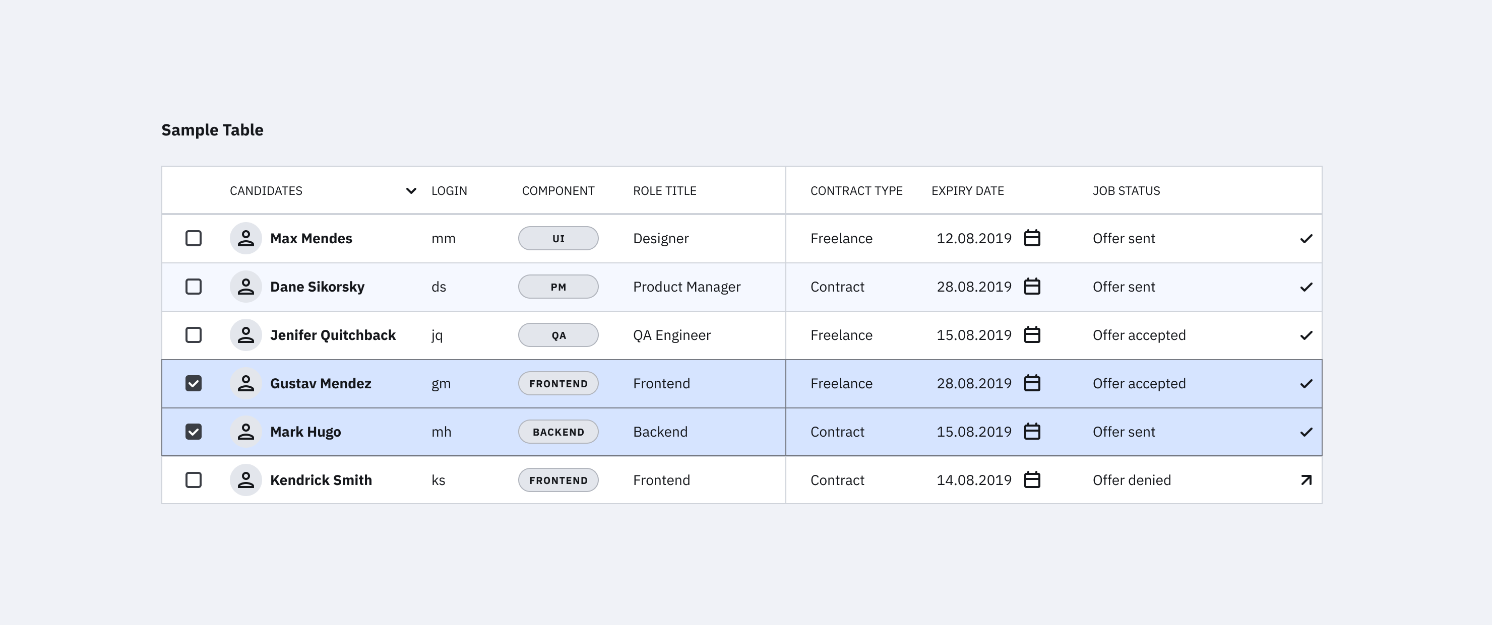
Figma cannot connect to a classic database, but we can use actual data with some preparation. You can use the Google Sheets Sync plugin and just add actual content there. By simply naming our layers with #columnname, run the plugin, add the link, and hit sync. And boom, there you go. There is also a Plugin for Airtable and Notion Sync working pretty much in the same way.

In general, we should test components with different content such as ideal state, little content, heavy content, empty, error, and loading states where applicable. I made a checklist for components you can use before release.

Working with actual data gives us a good idea of potential shortcomings. We can also see if the database needs some grooming or if the image pool needs a bit of love and attention to live up to the brand promise.

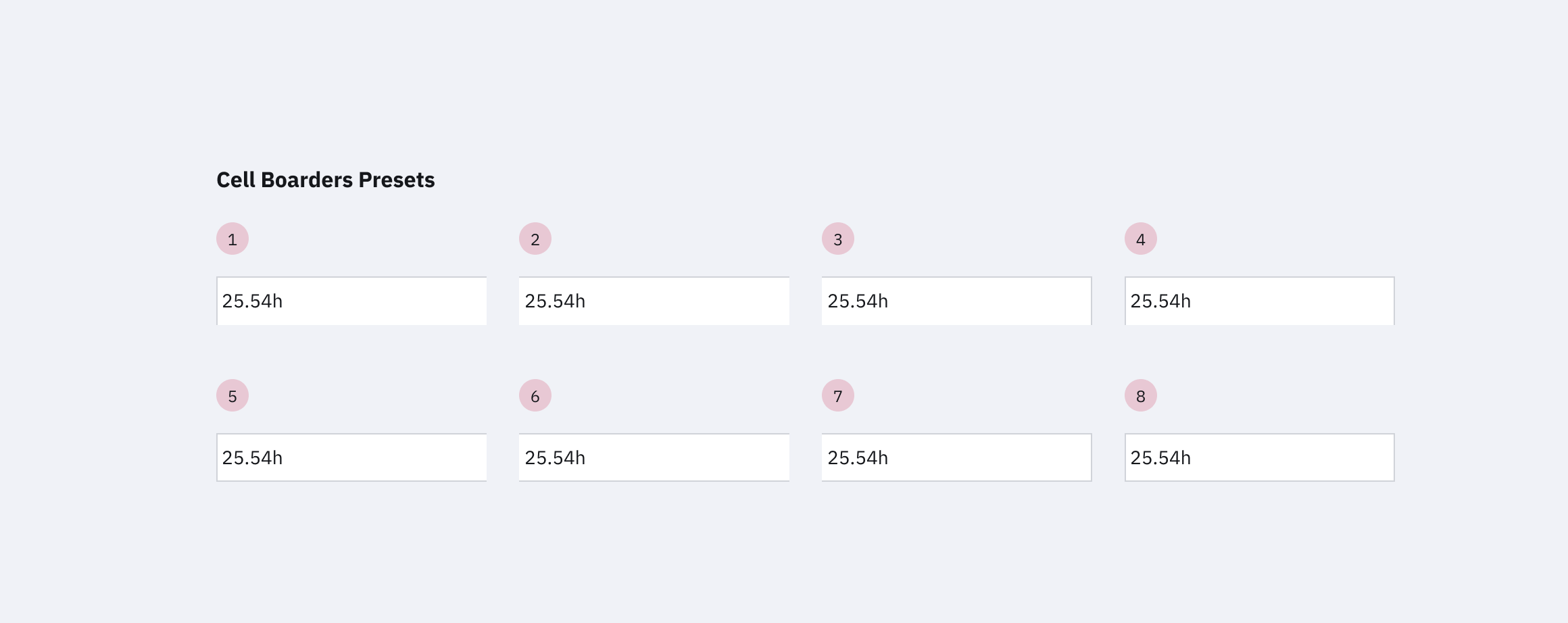
6. You Might Want To Point Out Soft Grid vs. Hard Grid To Us

When we click on Grids, Figma adds this px grid to the background. Order! Structure! As a designer, you jump at this, and as you were told to space with 8pt, you use the grid.

So we have this grid, which is why many designers jump to conclusions using a hard grid to set their spacing (it can be used for other alignment and handy in mobile setup, though). We have no spacing blocks or cubes to create a soft grid, we can set this by hand, though, and nudge in steps of 8, but that is about it.

Tip: In Figma, we can alter the nudge amount. Press Cmd + / and type “nudge” and change to 8. Make sure to keep alt pressing when nudging to see the distances. By pressing shift and up and down arrows, we then nudge in, e.g., 8pt steps.

Opportunities Between Design And Code

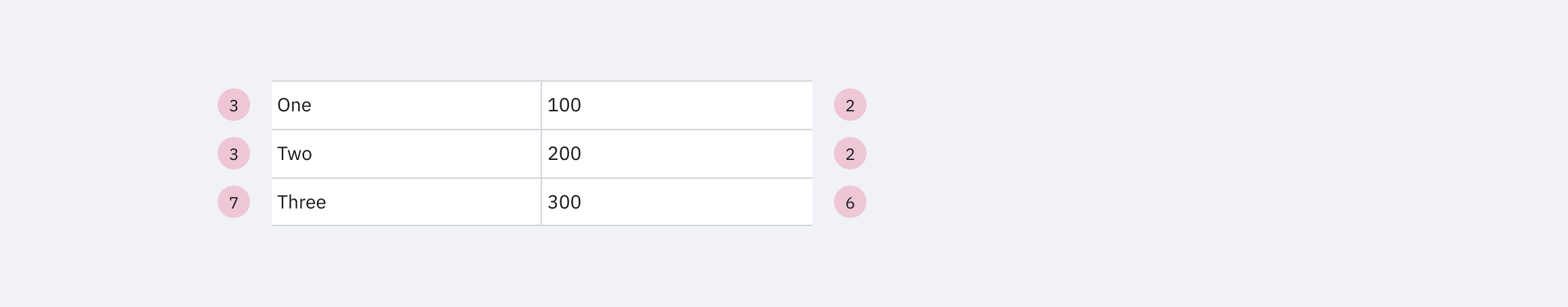
How Does Spacing Work For You In CSS?

Feel free to point out (preferably at the beginning of the project) that there is no such magic background grid in CSS and that the spacing system means measuring in spacing blocks from element to element (including the line height!). Or, in other words, explain the difference between the hard grid vs. the soft Grid that we use later in UI Design and CSS.

And yet again: Use the Figma Tokens Plugin.

Here we can just pull the real spacing system with spacing tokens and apply it to our components. We can also set up our own tokens just in Figma right in the plugin.

Note: We cannot set line height in Figma to something like 1.5 notation! By default, it uses px. But we can cheat a little and use %, so 1.5 in CSS would be 150% in Figma. You will still find the px value only in the inspect tab.

Opportunities Between Design And Code

Explain It!

So as a developer, you might find that the line height is randomly set to 1. This is a desperate design attempt to get rid of the “random” space we do not understand (yet). So it makes sense to remind (new) designers that UI Design is dynamic. Screen sizes change, and content length will vary (either because the content is added or translated into a new language). Thus, we can never assume a single line of the text remains a single line of text forever. Also, we do not want to create too many styles. So explain that working with the natural line height is just fine, and you will do the same in CSS.

8. All We Have In Figma Is PX

In Figma, we can only work with px, and we work at 1px=1pt. We do not have rem, em, or any other relative way to define things like font size. So if you see px everywhere in a UI Design, this does not mean we want it hard coded!!!

9. We Can Set Up Pretty Sweet Prototypes In Figma

We can create rather impressive prototypes directly from our design files in Figma. If you hit the play button in the file (top right), you can see them. We can link frames to new pages or overlays and also animate within component sets from variant to variant.

Opportunities Between Design And Code

As a developer, you will be able to navigate the file and pull out all information you need:

Pages

You can navigate the different frames on the canvas but note how there are different pages above the layers menu on the left. Every team uses pages differently, some for versions and sprints, some to structure the file into the design, components, and testing. In any case, ensure not to overlook the pages as they are the file’s structure.

Inspect Mode

When entering a file with view mode, you will see the inspect menu open per default. Click on an element, and you will be shown the distance to the nearest objects and the specs on the right-hand side menu.

You can switch between CSS, iOS, and Android.

When clicking on the main component, you will see the link to the code documentation (if applicable) and any comments in inspect mode.

This only shows up if it was added to the design tab’s component documentation. And you obviously only need this if you want to align UI and code components.

By the way, it works with any link. However, some such Github links create a nice custom button.

Styles Overview

Click on the canvas to get an overview of all styles in the file. Note that this only shows local styles; some might be pulled in from an external library. So the best is to check for style documentation (every design team should set this up for you) to make sure you have all information.

You should, however, still receive a general overview of all styles from your design team, including internal and external styles used now or in the future.

Jump To The Main Component

This is really important yet a bit hidden. Click on any instance on the canvas and then click on the diamond-shaped symbol sign, and you will jump to the main component and documentation. This is where you can get all information and measurements.

You should then be led to the Figma UI component library. This might be a local page or an external UI component document giving you all the necessary information and specs defined by the UI team. If you do not find such an overview, kindly ask your design team to set this up for you.

There is no magic automation for style and component overview in Figma. This needs to be set up and documented by the design team, and the format may vary.

Export Assets Of Any Size And Form

Assets can be exported to any asset in the format (JPG, PNG, SVG) and @size from the “view only” mode, so no bulk export by the design team is needed anymore.

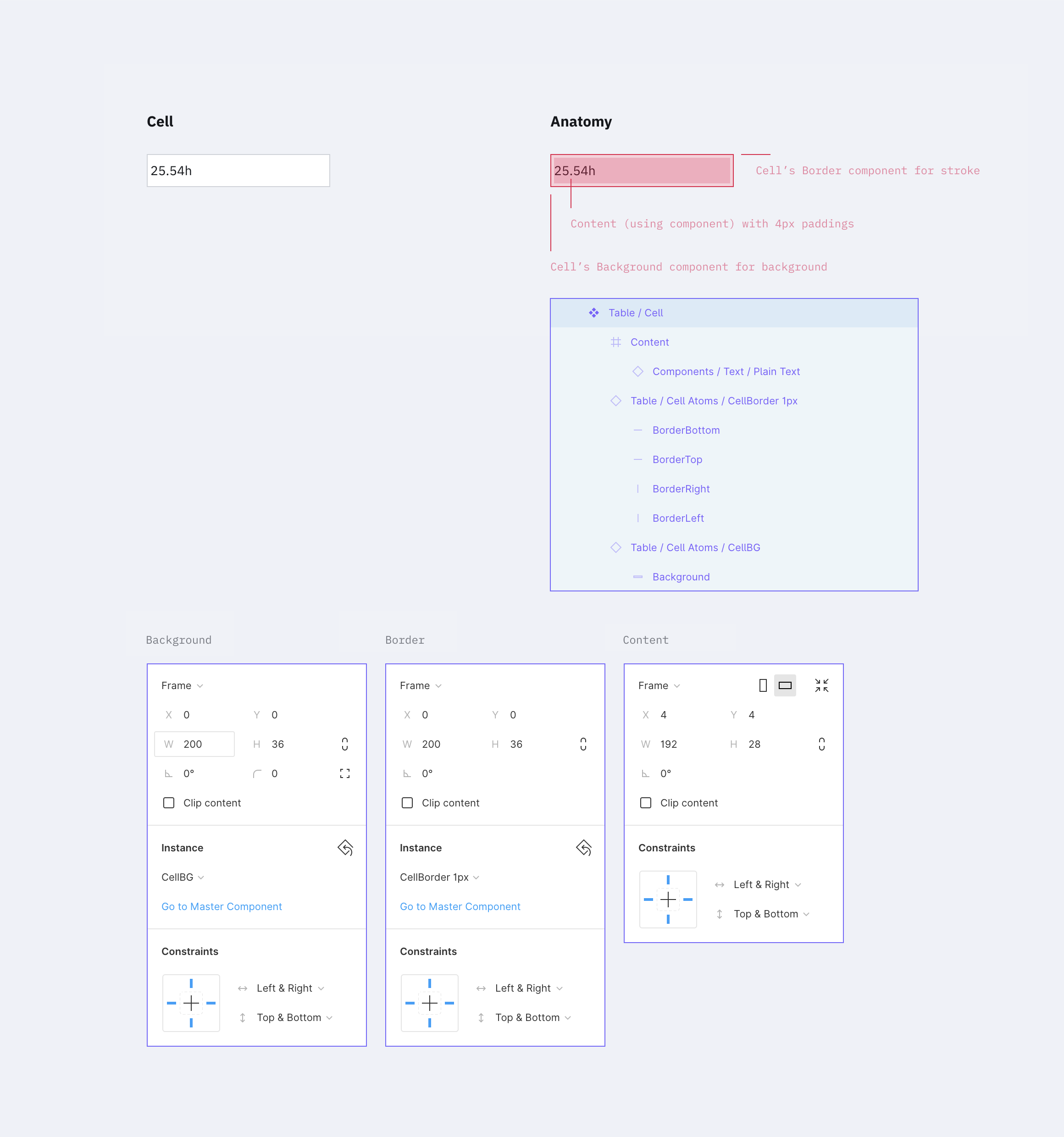
Tip: For a specific height or width, instead of 3x, 2x, just enter the width followed by w (e.g., 300w), and it will export it, keeping the image proportions. It also works for height (h).

Comment

Leave comments and discuss within your team.

Prototype

Hit the play button (top right corner of your design file), and you will jump to the presentation mode seeing your prototype in action. Usually, the designer was nice enough to add some flows and structure the prototype, so you get a good idea of different flows.

Tip: Individual links can be created from every flow of the prototype menu. I like using this to set up an overview of the design and testing stages. You can also link to any other team planning file here.

Stay In Touch!

If you liked this article, make sure to subscribe and visit me on moonlearning.io, where I teach about UX/UI Design+Figma. This article is also the base of my talk and workshop during the Smashing Conference New York, the 10th to the 13th of October 2022. See you there!

Creating Tables In Figma

Creating Tables In Figma

Creating Tables In Figma

Sasha Belichenko

In this tutorial, we will talk about how tables can be created in Figma by using components and Atomic Design methodology. We will also take a look at the basic elements of the table layout and how components can be included in the component library so that they can become part of the design system you are using.

To make it easy for you, I’ve prepared a mockup example that uses all of the components we need for this tutorial.

To follow along, you will need to have at least some understanding of the basic Figma concepts, its interface, and how to work with Figma components. However, if you’re new to Figma and working with table data, I recommend watching the “Getting Started” video to help you better understand Figma end-to-end, as well as the article “How To Architect A Complex Web Table” that was published not too long ago here on Smashing Magazine.

To simplify the scope of this tutorial, let’s assume that the colors, fonts, and effects already exist as styles in the Figma project you’re about to begin. In terms of Atomic Design, they are atoms. (To learn more, the folks at littleBits wrote a great article on the topic.)

The target audience for this tutorial are designers (UX, UI) who have either already adopted Figma into their workflows or are planning to try Figma in their next design projects but aren’t sure how to get started.

So, without further ado, let’s dig in!

Quick Note: While writing this article, Figma introduced plugins. At the time of publishing, there weren’t any good ones for working with tables, but things might change fast. Who knows, maybe this article will actually help an aspiring Figma plugin developer to create a really neat Figma Tables plugin, or at least, I hope it will. 😉

Introduction

Imagine the table as an organism. The table cell is then a molecule which is comprised of individual atoms. In design terms, they’re cell properties.

So, let’s start with the cell. It has three properties:

  1. Background
  2. Border
  3. Content

Now we’ll take a closer look at each one of them.

Background

The background will be a separate component in Figma. The size doesn’t really matter since we can stretch the component as we need, but let’s begin with setting the size to 100×36 pixels.

In this component, add a rectangle of the same size as the component itself. It will be the only object inside the component. We need to attach the rectangle’s borders to the component’s borders by using constraints (set constraints to “Left & Right” and “Top & Bottom” at the right panel in the Constraints section), so that the rectangle stretches automatically to the size of the component.

If you’d like to see this in action, watch this tutorial on how the constraints work in Figma.

The Background Component
The Background Component (the ‘atom’) (Large preview)

The fill color of the rectangle will determine the background color of the cell. Let’s pick the white color for it. I recommend choosing that color from the color styles that are configured at the beginning of the project.

Background color
Changing the background color (Large preview)

Border

This one is a bit trickier than the background. You can’t just create one rectangle with a stroke. We may need different kinds of borders: one for the separate cells (with borders around), one for the whole row of cells with only top and bottom borders, or one for the table header that we might want to separate from the rest with a wider line. There are many options.

Border properties:

  • Border line (left, right, top, bottom, or absence of any of them)
  • Line width
  • Line color
  • Line style

Each line within the cell border might havea different width, color, and style. For example, the left one could be a continuous red line, and the top one a dotted grey line.

Let’s create a component with a size of 100×36 pixels (the same as we did before). Inside the component, we need to add 4 lines for each border. Now pay attention to how we are going to do this.

  1. Add a line for the bottom border with the length of the component width;
  2. Set its position to the bottom border and constraints to stretch horizontally and stick to the bottom border;
  3. For the top border, duplicate the line for the bottom border, rotate it by 180 degrees and stick to the top of the component. (Don’t forget to change its constraints to stick to the top and stretch horizontally.);
  4. Next, for the left border, simply rotate by -90 degrees and set its position and constraints to be at the left side sticking to the left border and stretching vertically;
  5. Last but not least, you can create the right border by rotating it by 90 degrees and setting its position and constraints. Set stroke color and stroke width for each line to gray (select from the color styles) and 1 pixel respectively.

Note: You may be asking yourself why we rotated the line for the bottom border. Well, when you change the stroke width for a line in Figma, it will rise. So we had to set this “rise” direction to the center of the component. Changing the line’s stroke width (in our case it is the border size) won’t expand outside the component (cell).

Now we can hide or customize the styles separately for every border in the cell.

The Border Component
A border component with 1px stroke (Large preview)

If your project has several styles for table borders (a few border examples shown below), you should create a separate component for each style. Simply create a new master component as we did before and customize it the way you need.

Border Styles
A few extra examples of border styles. Note that the white background is not included in the component. (Large preview)

The separate stroke component will save up lots of your time and add scalability. If you change the stroke color inside the master component, the whole table will adjust. Same as with the background color above, each individual cell can have its own stroke parameters.

Border’s width and color
Changing border’s width and color (Large preview)

Content

This is the most complex component of all.

We need to create all possible variations of the table content in the project: plain text, a text with an icon (left or right, different alignment), checkboxes, switches, and any other content that a cell may possibly contain. To simplify this tutorial, please check the components in the mockup file. How to create and organize components in Figma is a topic for another article.

However, there are a few requirements for content components:

  • Components should stretch easily both vertically and horizontally to fit inside a cell;
  • The minimum size of the component should be less than the default cell size (especially height, keep in mind possible cell paddings);
  • Avoid any margins, so the components can align properly inside a cell;
  • Avoid unnecessary backgrounds because a cell itself has it already.
Content components examples
Examples of cell content in components. This is not a complete list; you can use most of the components of your design system inside a table. (Large preview)

Content components can be created gradually: start with the basic ones like text components and add new ones as the project grows in size.

The reason we want the content to be in components is the same as with other elements — it saves uptime. To change the cell’s content, we just need to switch it in the component.

Changing the component inside the cell
Editing the table using cells components (Large preview)

Creating A Cell Component

We created all the atoms we need: background, border, content. It’s time to create a cell component, i.e. the molecule made from atoms. Let’s gather all the components in a cell.

The cell component
The cell component (the ‘molecule’) (Large preview)

Set the background component as the bottom layer and stretch it to the whole cell size (set constraints to “Left & Right” and “Top & Bottom”).

Add the border component with the same constraints as the background component.

Now to the most complicated part — the content content.

The cell has paddings, so you need to make a frame with the component’s content. That frame should be stretched to the whole cell size except for the paddings. The content component should also be stretched to the whole frame size. The content itself needs to be deprived of any margins, so all paddings will be set by the cell.

At the end of the day, cell paddings are the only property in a component that we will set only once without an opportunity to change it later. In the example above, I made it 4px for all sides.

Note: As a fix, you can create columns with empty cells (with no content and width of 16px for example) left and right to the column where extra margin is needed. Or if your table’s design allows, you can add horizontal paddings inside the cell component. For example, cells in Google Material Design have 16px paddings by default.

Don’t forget to remove the “Clip content” option for the cell and frame (this can be done at the right-hand panel in the Properties section). The cell’s content can go out of its borders; for example, when a dropdown is inside your cell and you want to show its state with a popup.

Note: We’ll be using this cell style as the main one. Don’t worry if your table has additional styles — we’ll cover that in the Table States and Components, Not Overrides sections.

Cell Options For A Standard Table

This step could be optional but if your table needs states then you can’t go without it. And even more so if there is more than one border style in the table.

So let’s create additional cell components from which it’d be easier to build up a table. When working with a table, we will select the appropriate component depending on its position in the table (e.g. depending on the type of borders).

In order to do that, let’s take our cell component and create eight more masters from it. We also need to disable the appropriate layers responsible for borders. The result should look like the image below.

Cell options
The cell options we need to build a table. Note that there could be a few extra depending on your table borders styles. (Large preview)

The top row is for the cells on top and in the middle of the table. The bottom row is only for the cells at the bottom. This way we’ll be able to put the cells one after another with no gaps and keep the same stroke width.

A few examples:

The First example
If each cell in the table has a border, we’d only need cells 1, 4, 5 and 8. (Large preview)
The Second example
If there are merged cells or border absence, we must apply the rest 2 and 3 cells as well as 6 and 7 to the bottom row. (Large preview)
The Third example
If the table design considers the absence of vertical borders, cells 2 and 6 would be enough. (Large preview)

Note: For each border style created above, it’d be good to add master components like the ones described earlier.

So we have excluded the necessity of overriding cell’s instances (disabling the appropriate layers, to be precise). Instead of that, we use various components. Now if, for example, a column uses a different style from the default (the fill color or border), you can choose this column and simply change the relative component. And everything will be alright. On the opposite side, changing a border of each cell manually (disabling the appropriate borders) is a pain you don’t want to bother with.

Now we are ready to create tables (in terms of Atomic Design — organisms) from the various cell components (molecules) we made.

Customizing The Table

Changing the row’s height in the whole table is relatively easy: highlight the table, change the element height (in this case, the cell’s height, H in the right-hand panel in the Properties section), and then change the vertical margin from the element to 0. That’s it: changing the line height took two clicks!

Changing the row height
Changing the row height for the whole table (Large preview)

Changing the column width: highlight the column and change the width size. After moving the rest of the table close up, select the whole table by using the Tide Up option in the Alignment panel as well as the first item in the dropdown list under the rightmost icon.

Changing the column width
Changing the column width. (Large preview)

Note: I wouldn’t recommend grouping rows and columns. If you change the column size extending the elements, you’ll get fractional values for width and height. If you don’t group them and snap to the pixel grid, the cell size will remain an integer number.

The background color, stroke type, and content data can be changed in the appropriate component or in one of the eight cells master components (cells that had different stroke styles). The only parameter that can’t be changed right away is the cell margins, e.g. content paddings. The rest are easily customizable.

Components, Not Overrides

Looking at what we got in the end, it might seem like overkill. And it is if there is only one table in your project. In this case, you can simply create one cell component and leave the background and stroke components off. Simply include them in the cell component, create the table and do the necessary customization for each separate cell.

But if components are included in a library that is used by a number of other files, here comes the most interesting stuff.

Note: *I do not recommend changing the background color and stroke in components’ instances. Change them only in the master. By doing so, those instances with overrides won’t get updated. This means you would have to do that manually and that’s what we’re trying to avoid. So let’s stick to the master components.*

If we need to create an additional type of table cells (e.g. the table header), we add the necessary set of master components for cells with the appropriate styles (just like we did above with the eight cells that had different stroke styles), and use it. Yes, it takes longer than overriding components’ instances but this way you will avoid the case when changing the masters will apply those changes to all layouts.

Table States

Let’s talk about the states of the table’s elements. A cell can have three states: default, hover, and selected. Same for columns and rows.

If your project is relatively small, all states can be set by overrides inside instances of your table components. But if it’s a big one, and you’d want to be able to change the look of the states in the future, you’ll have to create separate components for everything.

You’ll need to add all eight cells with different stroke variants for each of the states (maybe less, depends on the stroke style). And yes, we’ll need separate components for the background color and the stroke for the states as well.

In the end, it’ll look similar to this:

Hover and Selected
The cells’ states (hover and selected) (Large preview)

Here’s where a bit of trouble comes in. Unfortunately, if we do everything as described above (when changing the component’s state from one to another), there is a risk of losing the cell’s content. We’ll have to update it apart from the case when the content type is the same as in the master cell. At this point, we can’t do anything about it.

Table with rows’ states
Table with various rows’ states. (Large preview)

I added tables in the mockup file that were made in a few different ways:

  • Using this tutorial (separate components for cells’ styles);
  • Using the cell component (components for borders, background, and content);
  • Using the cell component that unites everything (with only content components in addition).

Try to play around and change the cell’s styles.

Changing the state
Changing the state of the row. (Large preview)

Conclusion

If you’re using the same components library in several projects and you’ve got a reasonable number of tables in each of them, you can create a local copy of components (cells components with stroke styles and, if needed, cells components with different states), customize them, and use them in the project. The cell content can be set based on local components.

Also, if you’re using the table for one large project with different kinds of tables, all the above-mentioned components are easily scaled. The table components can be improved to infinity and beyond, like creating the cell states when hovering and other kinds of interactions.

Questions, feedback, thoughts? Leave a comment below, and I’ll do my best to help you!

Figma Table Mockup Download

As promised, I created a complete version of the Figma table mockup that you’re welcome to use for learning purposes or anything else you like. Enjoy!

Tables in Figma mockup design
Here’s a Figma table mockup that you can use for learning purposes — let the creativity begin!

Useful Resources

  • Figma YouTube Channel
    The official Figma channel on YouTube — it’s the first thing to watch if you are new to Figma.
  • Google Sheets Sync
    A Figma plugin that helps you get data from Google Sheets into your Figma file. This should work fine with the techniques from this tutoria, but you’ll need to invest some time into renaming all the text layers for this to work properly.
Smashing Editorial (mb, yk, il)