Particles Image Animation from Mathis Biabiany’s website

Editor’s note: We want to share more of the web dev and design community directly here on Codrops, so we’re very happy to start featuring Yuriy’s newest live coding sessions!

In this live stream of ALL YOUR HTML, I’m replicating the particles animation from Mathis Biabiany‘s website. The effect consists of 2^18 particles forming images and a colorful tunnel that creates an interesting transition from one image to another.

This coding session was streamed live on Oct 25, 2020.

Check out the live demo.

Original website: Mathis Biabiany

Developer of the original website: Mathis Biabiany

Support: https://www.patreon.com/allyourhtml

Setup: https://gist.github.com/akella/a19954…

The post Particles Image Animation from Mathis Biabiany’s website appeared first on Codrops.

Implementing WebGL Powered Scroll Animations

Editor’s note: We want to share more of the web dev and design community directly here on Codrops, so we’re very happy to start featuring Yuriy’s newest live coding sessions!

In this episode of ALL YOUR HTML, I’m reconstructing the beautiful scroll animations from Robin Noguier’s portfolio. Learn how to build a custom inertia scroll from scratch, using it in WebGL with some images from HTML, and adding a navigation to the whole experience.

This coding session was streamed live on Oct 18, 2020.

Original website: Robin Noguier

Developer of the original website: Lorenzo Cadamuro

Support: https://www.patreon.com/allyourhtml

Setup: https://gist.github.com/akella/a19954…

The post Implementing WebGL Powered Scroll Animations appeared first on Codrops.

Astounding Examples Of Three.js In Action

Three.js is a cross-browser JavaScript library and API used to create and display animated 3D computer graphics in a web browser using WebGL. You can learn more about it here. In today’s post we are sharing some amazing examples of this library in action for your inspiration and learning. Let’s get to it!

Your Web Designer Toolbox
Unlimited Downloads: 500,000+ Web Templates, Icon Sets, Themes & Design Assets


Particles & Waves

A very nicely done animation that responds to the mouse position.

See the Pen three.js canvas – particles – waves by deathfang (@deathfang) on CodePen.dark

Procedurally Generated Minimal Environment

A rotating mountain terrain grid animation.

See the Pen Procedurally generated minimal environment by Marc Tannous (@marctannous) on CodePen.dark

Particle Head

Similar to the particles and waves animation above, this one shows particles in the 3D shape of a head that moves with your mouse.

See the Pen WebGL particle head by Robert Bue (@robbue) on CodePen.dark

The Cube

Try to not spend hours playing this addictive game!

See the Pen The Cube by Boris Šehovac (@bsehovac) on CodePen.dark

Three.js Particle Plane and Universe

Here’s another one to play with using mouse movements, clicks and arrow keys.

See the Pen Simple Particle Plane & Universe :) by Unmesh Shukla (@unmeshpro) on CodePen.dark

Text Animation

A somewhat mind-boggling text animation that can also be controlled by your mouse.

See the Pen THREE Text Animation #1 by Szenia Zadvornykh (@zadvorsky) on CodePen.dark

Distortion Slider

Cool transition animation between slides. Click on the navigation dots to check it out.

See the Pen WebGL Distortion Slider by Ash Thornton (@ashthornton) on CodePen.dark

Torus Tunnel

This one will probably hurt your eyes if you look too long.

See the Pen Torus Tunnel by Mombasa (@Mombasa) on CodePen.dark

Three.js Round

This one is a beautifully captivating animation.

See the Pen three.js round 1 by alex baldwin (@cubeghost) on CodePen.dark

3D Icons

Nice animation of icons flying into becoming various words.

See the Pen Many Icons in 3D using Three.js by Yasunobu Ikeda a.k.a @clockmaker (@clockmaker) on CodePen.dark

WormHole

A great sci-fi effect featuring an infinite worm hole.

See the Pen WormHole by Josep Antoni Bover (@devildrey33) on CodePen.dark

Three.js + TweenMax Experiment

Another captivating animation that is difficult to walk away from.

See the Pen Three.js + TweenMax (Experiment) by Noel Delgado (@noeldelgado) on CodePen.dark

Three.js Point Cloud Experiment

Another particle-type animation that responds to mouse movements.

See the Pen Three Js Point Cloud Experiment by Sean Dempsey (@seanseansean) on CodePen.dark

Gravity

More 3D particles in a hypnotizing endless movement.

See the Pen Gravity (three.js / instancing / glsl) by Martin Schuhfuss (@usefulthink) on CodePen.dark

Rushing rapid in a forest by Three.js

For our last example, check out this somewhat simple geometric scene with an endlessly flowing waterfall.

See the Pen 33 | Rushing rapid in a forest by Three.js by Yiting Liu (@yitliu) on CodePen.dark

Are You Already Using Three.js In Your Projects?

Whether you are already using Three.js in your projects, are in the process of learning how to use it, or have been inspired to start learning it now, these examples should help you with further inspiration or to get a glimpse of how it can be done. Be sure to check out our other collections for more inspiration and insight into web design and development!

Recreating the “100 Days of Poetry” Effect with Shader, ScrollTrigger and CSS Grid

Editor’s note: We want to share more of the web dev and design community directly here on Codrops, so we’re very happy to start featuring Yuriy’s newest live coding sessions that he records twice a month plus the demo he creates during the session!

For this episode of ALL YOUR HTML, I decided to replicate the effect seen on 100 DAYS OF POETRY with the technologies I know. So I did a fragment shader for the background effect, then coded a dummy CSS grid, and connected both of them with the power of GSAP’s ScrollTrigger plugin. This is of course a really simplified version of the website, but I hope you will learn something from the process of recreating this.

This coding session was streamed live on Oct 4, 2020.

Check out the live demo.

Original website: https://100daysofpoetry.gallery/

By Keita Yamada https://twitter.com/p5_keita

Support: https://www.patreon.com/allyourhtml

Setup: https://gist.github.com/akella/a19954…

The post Recreating the “100 Days of Poetry” Effect with Shader, ScrollTrigger and CSS Grid appeared first on Codrops.

Kinetic Typography with Three.js

Kinetic Typography may sound complicated but it’s just the elegant way to say “moving text” and, more specifically, to combine motion with text to create animations.

Imagine text on top of a 3D object, now could you see it moving along the object’s shape? Nice! That’s exactly what we’ll do in this article ? we’ll learn how to move text on a mesh using Three.js and three-bmfont-text.

We’re going to skip a lot of basics, so to get the most from this article we recommend you have some basic knowledge about Three.js, GLSL shaders, and three-bmfont-text.

Basis

The main idea for all these demos is to have a texture with text, use it on a mesh and play with it inside shaders. The simplest way of doing it is to have an image with text and then use it as a texture. But it can be a pain to figure out the correct size to try to display crisp text on the mesh, and later to change whatever text is in the image.

To avoid all these issues, we can generate that texture using code! We create a Render Target (RT) where we can have a scene that has text rendered with three-bmfont-text, and then use it as the texture of a mesh. This way we have more freedom to move, change, or color text. We’ll be taking this route following the next steps:

  1. Set up a RT with the text
  2. Create a mesh and add the RT texture
  3. Change the texture inside the fragment shader

To begin, we’ll run everything after the font file and atlas are loaded and ready to be used with three-bmfont-text. We won’t be going over this since I explained it in one of my previous articles.

The structure goes like this:

init() {
  // Create geometry of packed glyphs
  loadFont(fontFile, (err, font) => {
    this.fontGeometry = createGeometry({
      font,
      text: "ENDLESS"
    });

    // Load texture containing font glyphs
    this.loader = new THREE.TextureLoader();
    this.loader.load(fontAtlas, texture => {
      this.fontMaterial = new THREE.RawShaderMaterial(
        MSDFShader({
          map: texture,
          side: THREE.DoubleSide,
          transparent: true,
          negate: false,
          color: 0xffffff
        })
      );

      // Methods are called here
    });
  });
}

Now take a deep breath, grab your tea or coffee, chill, and let’s get started.

Render Target

A Render Target is a texture you can render to. Think of it as a canvas where you can draw whatever is inside and place it wherever you want. Having this flexibility makes the texture dynamic, so we can later add, change, or remove stuff in it.

Let’s set a RT along with a camera and a scene where we’ll place the text.

createRenderTarget() {
  // Render Target setup
  this.rt = new THREE.WebGLRenderTarget(
    window.innerWidth,
    window.innerHeight
  );

  this.rtCamera = new THREE.PerspectiveCamera(45, 1, 0.1, 1000);
  this.rtCamera.position.z = 2.5;

  this.rtScene = new THREE.Scene();
  this.rtScene.background = new THREE.Color("#000000");
}

Once we have the RT scene, let’s use the font geometry and material previously created to make the text mesh.

createRenderTarget() {
  // Render Target setup
  this.rt = new THREE.WebGLRenderTarget(
    window.innerWidth,
    window.innerHeight
  );

  this.rtCamera = new THREE.PerspectiveCamera(45, 1, 0.1, 1000);
  this.rtCamera.position.z = 2.5;

  this.rtScene = new THREE.Scene();
  this.rtScene.background = new THREE.Color("#000000");

  // Create text with font geometry and material
  this.text = new THREE.Mesh(this.fontGeometry, this.fontMaterial);

  // Adjust text dimensions
  this.text.position.set(-0.965, -0.275, 0);
  this.text.rotation.set(Math.PI, 0, 0);
  this.text.scale.set(0.008, 0.02, 1);

  // Add text to RT scene
  this.rtScene.add(this.text);
 
  this.scene.add(this.text); // Add to main scene
}

Note that for now, we added the text to the main scene to render it on the screen.

Cool! Let’s make it more interesting and “paste” the scene over a shape next.

Mesh and render texture

For simplicity, we’ll first use as shape a BoxGeometry together with ShaderMaterial to pass custom shaders, time and the render texture uniforms.

createMesh() {
  this.geometry = new THREE.BoxGeometry(1, 1, 1);

  this.material = new THREE.ShaderMaterial({
    vertexShader,
    fragmentShader,
    uniforms: {
      uTime: { value: 0 },
      uTexture: { value: this.rt.texture }
    }
  });

  this.mesh = new THREE.Mesh(this.geometry, this.material);

  this.scene.add(this.mesh);
}

The vertex shader won’t be doing anything interesting this time; we’ll skip it and focus on the fragment instead, which is showing the colors of the RT texture. It’s inverted for now (1. - texture) to stand out from the background.

varying vec2 vUv;

uniform sampler2D uTexture;

void main() {
  vec3 texture = texture2D(uTexture, vUv).rgb;

  gl_FragColor = vec4(1. - texture, 1.);
}

Normally, we would just render the main scene directly, but with a RT we have to first render to it before rendering to the screen.

render() {
  ...

  // Draw Render Target
  this.renderer.setRenderTarget(this.rt);
  this.renderer.render(this.rtScene, this.rtCamera);
  this.renderer.setRenderTarget(null);
  this.renderer.render(this.scene, this.camera);
}

And now a box should appear on the screen where each face has the text on it:

Looks alright so far, but what if we could cover more text around the shape?

Repeating the texture

GLSL’s built-in function fract comes handy to make repetition. We’ll use it to repeat the texture coordinates when multiplying them by a scalar so it wraps between 0 and 1.

varying vec2 vUv;

uniform sampler2D uTexture;

void main() {
  vec2 repeat = vec2(2., 6.); // 2 columns, 6 rows
  vec2 uv = fract(vUv * repeat);

  vec3 texture = texture2D(uTexture, uv).rgb;
  texture *= vec3(uv.x, uv.y, 1.);

  gl_FragColor = vec4(texture, 1.);
}

Notice that we also multiply the texture by the uv components to visualize the modified texture coordinates.

We’re getting there, right? The text should also follow the object’s shape; here’s where time comes in. We need to add it to the texture coordinates, in this case to the x component so it moves horizontally.

varying vec2 vUv;

uniform sampler2D uTexture;
uniform float uTime;

void main() {
  float time = uTime * 0.75;
  vec2 repeat = vec2(2., 6.);
  vec2 uv = fract(vUv * repeat + vec2(-time, 0.));

  vec3 texture = texture2D(uTexture, uv).rgb;

  gl_FragColor = vec4(texture, 1.);
}

And for a sweet touch, let’s blend the color with the the background.

This is basically the process! RT texture, repetition, and motion. Now that we’ve looked at the mesh for so long, using a BoxGeometry gets kind of boring, doesn’t it? Let’s change it in the next final bonus chapter.

Changing the geometry

As a kid, I loved playing and twisting these tangle toys, perhaps that’s the reason why I find satisfaction with knots and twisted shapes? Let this be an excuse to work with a torus knot geometry.

For the sake of rendering smooth text we’ll exaggerate the amount of tubular segments the knot has.

createMesh() {
  this.geometry = new THREE.TorusKnotGeometry(9, 3, 768, 3, 4, 3);

  ...
}

Inside the fragment shader, we’ll repeat any number of columns we want just to make sure to leave the same number of rows as the number of radial segments, which is 3.

varying vec2 vUv;

uniform sampler2D uTexture;
uniform float uTime;

void main() {
  vec2 repeat = vec2(12., 3.); // 12 columns, 3 rows
  vec2 uv = fract(vUv * repeat);

  vec3 texture = texture2D(uTexture, uv).rgb;
  texture *= vec3(uv.x, uv.y, 1.);

  gl_FragColor = vec4(texture, 1.);
}

And here’s our tangled torus knot:

Before adding time to the texture coordinates, I think we can make a fake shadow to give a better sense of depth. For that we’ll need to pass the position coordinates from the vertex shader using a varying.

varying vec2 vUv;
varying vec3 vPos;

void main() {
  vUv = uv;
  vPos = position;

  gl_Position = projectionMatrix * modelViewMatrix * vec4(position, 1.);
}

We now can use the z-coordinates and clamp them between 0 and 1, so the regions of the mesh farther the screen get darker (towards 0), and the closest lighter (towards 1).

varying vec3 vPos;

void main() {
  float shadow = clamp(vPos.z / 5., 0., 1.);

  gl_FragColor = vec4(vec3(shadow), 1.);
}

See? It sort of looks like white bone:

Now the final step! Multiply the shadow to blend it with the texture, and add time again.

varying vec2 vUv;
varying vec3 vPos;

uniform sampler2D uTexture;
uniform float uTime;

void main() {
  float time = uTime * 0.5;
  vec2 repeat = -vec2(12., 3.);
  vec2 uv = fract(vUv * repeat - vec2(time, 0.));

  vec3 texture = texture2D(uTexture, uv).rgb;

  float shadow = clamp(vPos.z / 5., 0., 1.);

  gl_FragColor = vec4(texture * shadow, 1.);
}

Fresh out of the oven! Look at this sexy torus coming out of the darkness. Internet high five!


We’ve just scratched the surface making repeated tiles of text, but there are many ways to add fun to the mixture. Could you use trigonometry or noise functions? Play with color? Text position? Or even better, do something with the vertex shader. The sky’s the limit! I encourage you to explore this and have fun with it.

Oh! And don’t forget to share it with me on Twitter. If you got any questions or suggestions, let me know.

Hope you learned something new. Till next time!

References and Credits

The post Kinetic Typography with Three.js appeared first on Codrops.

Interactive WebGL Hover Effects

I love WebGL, and in this article I will explain one of the cool effects you can make if you master shaders. The effect I want to recreate is originally from Jesper Landberg’s website. He’s a really cool dude, make sure to check out his stuff:

So let’s get to business! Let’s start with this simple HTML:

<div class="item">
    <img src="img.jpg" class="js-image" alt="">
    <h2>Some title</h2>
    <p>Lorem ipsum.</p>
</div>
<script src="app.js"></script>

Couldn’t be any easier! Let’s style it a bit to look prettier:

All the animations will happen in a Canvas element. So now we need to add a bit of JavaScript. I’m using Parcel here, as it’s quite simple to get started with. I’ll use Three.js for the WebGL part.

So let’s add some JavaScript and start with a basic Three.js setup from the official documentation:

import * as THREE from "three";

var scene = new THREE.Scene();
var camera = new THREE.PerspectiveCamera( 75, window.innerWidth/window.innerHeight, 0.1, 1000 );

var renderer = new THREE.WebGLRenderer();
renderer.setSize( window.innerWidth, window.innerHeight );
document.body.appendChild( renderer.domElement );


camera.position.z = 5;

var animate = function () {
	requestAnimationFrame( animate );

	cube.rotation.x += 0.01;
	cube.rotation.y += 0.01;

	renderer.render( scene, camera );
};

animate();

Let’s style the Canvas element:

body { margin: 0; }

canvas { 
	display: block; 
	position: fixed;
	z-index: -1; // put it to background
	left: 0; // position it to fill the whole screen
	top: 0; // position it to fill the whole screen
}

Once you have all this in place, you can just run it with `parcel index.html`. Now, you wouldn’t see much, its an empty 3D scene so far. Let’s leave the HTML for a moment, and concentrate on the 3D scene for now.

Let’s create a simple PlaneBufferGeometry object with an image on it. Just like this:

let TEXTURE = new TextureLoader().load('supaAmazingImage.jpg'); 
let mesh = new Mesh(
	new PlaneBufferGeometry(), 
	new MeshBasicMaterial({map: TEXTURE})
)

And now we’ll see the following:

Obviously we are not there yet, we need that color trail following our mouse. And of course, we need shaders for that. If you are interested in shaders, you’ve probably come across some tutorials on how to displace images, like displacing on hover or liquid distortion effects.

But we have a problem: we can only use shaders on (and inside) that image from the example above. But the effect is not constrained to any image borders, but rather, it’s fluid, covering more area, like the whole screen.

Postprocessing to the rescue

It turns out that the output of the Three.js renderer is just another image. We can make use of that and apply the shader displacement on that output!

Here is the missing part of the code:

// set up post processing
let composer = new EffectComposer(renderer);
let renderPass = new RenderPass(scene, camera);
// rendering our scene with an image
composer.addPass(renderPass);

// our custom shader pass for the whole screen, to displace previous render
let customPass = new ShaderPass({vertexShader,fragmentShader});
// making sure we are rendering it.
customPass.renderToScreen = true;
composer.addPass(customPass);

// actually render scene with our shader pass
composer.render()
// instead of previous
// renderer.render(scene, camera);

There are a bunch of things happening here, but it’s pretty straightforward: you apply your shader to the whole screen.

So let’s do that final shader with the effect:

// get small circle around mouse, with distances to it
float c = circle(uv, mouse, 0.0, 0.2);
// get texture 3 times, each time with a different offset, depending on mouse speed:
float r = texture2D(tDiffuse, uv.xy += (mouseVelocity * .5)).x;
float g = texture2D(tDiffuse, uv.xy += (mouseVelocity * .525)).y;
float b = texture2D(tDiffuse, uv.xy += (mouseVelocity * .55)).z;
// combine it all to final output
color = vec4(r, g, b, 1.);

You can see the result of this in the first demo.

Applying the effect to several images

A screen has its size, and so do images in 3D. So what we need to do now is to calculate some kind of relation of those two.

Just like I did in my previous article, we can make a plane with a width of 1, and fit it exactly to the screen width. So practically, we have WidthOfPlane=ScreenSize.

For our Three.js scene, this means that if want an image with a width of 100px on the screen, we will make a Three.js object with width of 100*(WidthOfPlane/ScreenSize). That’s it! With this kind of math we can also set some margins and positions easily.

When the page loads, I will loop through all the images, get their dimensions, and add them to my 3D world:

let images = [...document.querySelectorAll('.js-image')];
images.forEach(image=>{
	// and we have the width, height and left, top position of the image now!
	let dimensions = image.getBoundingClientRect();
	// hide original image
	image.style.visibility = hidden;
	// add 3D object to your scene, according to its HTML brother dimensions
	createMesh(dimensions);
})

Now it’s quite straightforward to make this HTML-3D hybrid.

Another thing that I added here is mouseVelocity. I used it to change the radius of the effect. The faster the mouse moves, the bigger the radius.

To make it scrollable, we would just need to move the whole scene, the same amount that the screen was scrolled. Using that same formula I mentioned before: NumberOfPixels*(WidthOfPlane/ScreenSize).

Sometimes it’s even easier to make WidthOfPlane equal to ScreenSize. That way, you end up with exactly the same numbers in both worlds!

Exploring different effects

With different shaders you can come up with any kind of effect with this approach. So I decided to play a little bit with the parameters.

Instead of separating the image in three color layers, we could simply displace it depending on the distance to the mouse:

vec2 newUV = mix(uv, mouse, circle); 
color = texture2D(tDiffuse,newUV);

And for the last effect I used some randomness, to get a pixelated effect around the mouse cursor.

In this last demo you can switch between effects to see some modifications you can make. With the “zoom” effect, I just use a displacement, but in the last one, I also randomize the pixels, which looks kinda cool to me!

I’d be happy to see your ideas for this animation. What kind of effect would you do with this technique?

Interactive WebGL Hover Effects was written by Yuriy Artyukh and published on Codrops.

Create a Wave Motion Effect on an Image with Three.js

Waves! Because who does not enjoy the visual comfort an oscillating motion has on the human eye? Well, I do and for this tutorial, I would like to explain how to make waves on a 3D plane with Three.js using simplex noise.

To keep things short, we’ll just focus on the plane effect and not on the smooth scrolling or setup required to synchronize the DOM with WebGL. For these, check out Jesper Landberg’s codepen on smooth scrolling, and Luigi De Rosa’s article on how EPIC mixed WebGL and the DOM for WeCargo.

We’ll asume you have some basic understanding of Three.js, vertex and fragment shaders, so we’ll skip things like how to set up a scene.

Now let’s begin.

Creating the mesh

First, we’ll create a mesh using a PlaneGeometry and a ShaderMaterial.

Since we want to add a texture later, we’ll give out PlaneGeometry the same proportions as our 400×600 image. So, 0.4 for the width and 0.6 for the height. Having the same proportions makes it so the texture doesn’t stretch.

this.geometry = new THREE.PlaneGeometry(0.4, 0.6, 16, 16);
this.material = new THREE.ShaderMaterial({
  vertexShader,
  fragmentShader,
  uniforms: {
    uTime: { value: 0.0 }
  },
  wireframe: true,
});
this.mesh = new THREE.Mesh(this.geometry, this.material);
this.scene.add(this.mesh);

As a performance side note, if you are rendering more than one element to a scene, make sure to reuse the geometry object.

Making some noise

We’re going to displace the plane using 3D simplex noise.

Our simplex noise function snoise, outputs values between -1 and 1 based on the position values you give it.

Simplex noise is amazing because it’s random and seamless! So it’s really useful to create organic patterns. Which is exactly what we want for our wave effect.

Now inside the vertex shader. Using the vertex positions of the plane, we’re going to sample simplex noise to get a wave distortion, adjusting its frequency and amplitude to control it. The frequency will only change the x vector component to make horizontal waves on the plane and adding a time uniform to make them move. For the distortion to take place forwards and backwards, we need to add the value to the z vector component.

varying vec2 vUv;
uniform float uTime;

void main() {
  vUv = uv;

  vec3 pos = position;
  float noiseFreq = 3.5;
  float noiseAmp = 0.15; 
  vec3 noisePos = vec3(pos.x * noiseFreq + uTime, pos.y, pos.z);
  pos.z += snoise(noisePos) * noiseAmp;

  gl_Position = projectionMatrix * modelViewMatrix * vec4(pos, 1.);
}

And that’s really it for the motion! Even though it’s moving, the effect doesn’t quite sell because the inside looks flat.

To give that extra flare, as it is displaced, we need to modify colors accordingly. But before we do that, let’s add some pretty image!

Adding the texture

First, let’s create a new uniform that holds the texture for the ShaderMaterial.

this.material = new THREE.ShaderMaterial({
  vertexShader,
  fragmentShader,
  uniforms: {
    uTime: { value: 0.0 },
    uTexture: { value: new THREE.TextureLoader().load(img) },
  },
});

Second, let’s sample the texture in the fragment shader.

varying vec2 vUv;
uniform sampler2D uTexture;

void main() {
  vec3 texture = texture2D(uTexture, vUv).rgb;
  gl_FragColor = vec4(texture, 1.);
}

It looks solid already. Cool! Let’s go a step further and make it even more interesting by displacing the texture coordinates.

Displacing the texture coordinates

We can use the noise value from the vertex shader, pass it to the fragment shader, and add it to the texture coordinates so the image follows the motion of the displacement.

To share the distortion data from the vertex shader to the fragment shader we’ll use a varying, and for now let’s disable the vertex movement so we can appreciate more the texture displacement.

varying vec2 vUv;
varying float vWave;
uniform float uTime;

void main() {
  vUv = uv;

  vec3 pos = position;
  float noiseFreq = 3.5;
  float noiseAmp = 0.15; 
  vec3 noisePos = vec3(pos.x * noiseFreq + uTime, pos.y, pos.z);
  pos.z += snoise(noisePos) * noiseAmp;
  vWave = pos.z; // Off it goes!

  gl_Position = projectionMatrix * modelViewMatrix * vec4(position, 1.);
}

A new variable inside the fragment shader will be needed to scale down the distortion so it’s not too sharp.

varying vec2 vUv;
varying float vWave;
uniform sampler2D uTexture;

void main() {
  float wave = vWave * 0.2;
  vec3 texture = texture2D(uTexture, vUv + wave).rgb;
  gl_FragColor = vec4(texture, 1.);
}

See how the texture moves in the same way but in two dimensions? What if instead of moving all the texture coordinates, we only did it for one color channel to give a more futuristic vibe?

Splitting the color channel

To move one color channel, we’ll need to separate each color vector of the texture, add the wave value to one of their coordinates, and combine them back together. I’ll try it on the blue channel, but you can experiment with any of them.

varying vec2 vUv;
varying float vWave;
uniform sampler2D uTexture;

void main() {
  float wave = vWave * 0.2;
  // Split each texture color vector
  float r = texture2D(uTexture, vUv).r;
  float g = texture2D(uTexture, vUv).g;
  float b = texture2D(uTexture, vUv + wave).b;
  // Put them back together
  vec3 texture = vec3(r, g, b);
  gl_FragColor = vec4(texture, 1.);
}

Now the movement is happening just on blue channel of the texture. Spooky!

Finally, we can enable again the vertex distortion to get the final result. Aaaand here it is:

I hope you made it until here! This is just one of countless possibilities you can do with shaders and Three.js. For example, in the second demo, I took a different approach making transitions using displacement maps — if you’re interested in it, perhaps we can leave that for another time.

Make sure to tweak the values to get different results, mess with the noise, or use another kind of noise (psst psst Worley), create something and have fun with it! Oh, and don’t forget to share it with me on Twitter. If you got any questions or suggestions, please let me know, too.

Hope you learned something new. Until next time!

References and Credits

Create a Wave Motion Effect on an Image with Three.js was written by Mario Carrillo and published on Codrops.

How to Create a Physics-based 3D Cloth with Cannon.js and Three.js

Following my previous experiment where I’ve showed you how to build a 3D physics-based menu, let’s now take a look at how to turn an image into a cloth-like material that gets distorted by wind using Cannon.js and Three.js.

In this tutorial, we’ll assume that you’re comfortable with Three.js and understand the basic principles of the Cannon.js library. If you aren’t, take a look at my previous tutorial about Cannon and how to create a simple world using this 3D engine.

Before we begin, take a look at the demo that shows a concrete example of a slideshow that uses the cloth effect I’m going to explain. The slideshow in the demo is based on Jesper Landberg’s Infinite draggable WebGL slider.

Preparing the DOM, the scene and the figure

I’m going to start with an example from one of my previous tutorials. I’m using DOM elements to re-create the plane in my scene. All the styles and positions are set in CSS and re-created in the canvas with JavaScript. I just cleaned some stuff I don’t use anymore (like the data-attributes) but the logic is still the same:

// index.html
<section class="container">
    <article class="tile">
        <figure class="tile__figure">
            <img src="path/to/my/image.jpg" 
                class="tile__image" alt="My image" width="400" 
                height="300" />
        </figure>
    </article>
</section>

And here we go:

Creating the physics world and update existing stuff

We’ll update our Scene.js file to add the physics calculation and pass the physics World as an argument to the Figure object:

// Scene.js’s constructor
this.world = new C.World();
this.world.gravity.set(0, -1000, 0);

For this example, I’m using a large number for gravity because I’m working with big sized objects.

// Scene.js’s constructor
this.figure = new Figure(this.scene, this.world);

// Scene.js's update method
this.world.step(1 / 60);

// We’ll see this below!
this.figure.update()

Let’s do some sewing

In the last tutorial on Cannon, I talked about rigid bodies. As its name suggests, you give an entire object a shape that will never be distorted. In this example, I will not use rigid bodies but soft bodies. I’ll create a new body per vertex, give it a mass and connect them to recreate the full mesh. After that, like with the rigid bodies, I copy each Three vertices’ position with Cannon’s body position and voilà!

Let’s start by updating the subdivision segments of the mesh with a local variable “size”: 

const size = 8;

export default class Figure {
    constructor(scene, world) {
    this.world = world

//…

// Createmesh method
this.geometry = new THREE.PlaneBufferGeometry(1, 1, size, size);

Then, we add a new method in our Figure Class called “CreateStitches()” that we’ll call it just after the createMesh() method. The order is important because we’ll use each vertex coordinate to set the base position of our bodies.

Creating the soft body

Because I’m using a BufferGeometry rather than Geometry, I have to loop through the position attributes array based on the count value. It limits the number of iterations through the whole array and improves performances. Three.js provides methods that return the correct value based on the index.

createStitches() {
    // We don't want a sphere nor a cube for each point of our cloth. Cannon provides the Particle() object, a shape with ... no shape at all!
    const particleShape = new C.Particle();
    
    const { position } = this.geometry.attributes;
    const { x: width, y: height } = this.sizes;

    this.stitches = [];

    for (let i = 0; i < position.count; i++) {

      const pos = new C.Vec3(
        position.getX(i) * width,
        position.getY(i) * height,
        position.getZ(i)
      );

      const stitch = new C.Body({
          
        // We divide the mass of our body by the total number of points in our mesh. This way, an object with a lot of vertices doesn’t have a bigger mass. 
        mass: mass / position.count,
        
        // Just for a smooth rendering, you can drop this line but your cloth will move almost infinitely.
        linearDamping: 0.8,
        
        position: pos,
        shape: particleShape,

        // TEMP, we’ll delete later
        velocity: new C.Vec3(0, 0, -300)
      });

      this.stitches.push(stitch);
      this.world.addBody(stitch);
    }
}

Notice that we multiply by the size of our mesh. That’s because, in the beginning, we set the size of our plane to a size of 1. So each vertex has its coordinates normalized and we have to multiply them afterwards.

Updating the mesh

As we need to set our position in normalized coordinates, we have to divide by the width and height values and set it to the bufferAttribute.

// Figure.js
update() {
    const { position } = this.geometry.attributes;
    const { x: width, y: height } = this.sizes;

    for (let i = 0; i < position.count; i++) {
      position.setXYZ(
        i,
        this.stitches[i].position.x / width,
        this.stitches[i].position.y / height,
        this.stitches[i].position.z
      );
    }

    position.needsUpdate = true;
}

And voilà! Now you should have a falling bunch of unconnected points. Let’s change that by just setting the first row of our stitches to a mass of zero.

for (let i = 0; i < position.count; i++) {
      const row = Math.floor(i / (size + 1));

// ...

const stitch = new C.Body({
    mass: row === 0 ? 0 : mass / position.count,

// ...

I guess you noticed I increased the size plus one. Let’s take a look at the wireframe of our mesh:

As you can notice, when we set the number of segments with the ‘size’ variable, we have the correct number of subdivisions. But we are working on the mesh so we have one more row and column. By the way, if you inspect the count value we used above, we have 81 vertices (9*9), not 64 (8*8).

Connecting everything

Now, you should have a falling bunch of points falling down but not the first line! We have to create a DistanceConstraint from each point to their neighbour.

// createStitches()
for (let i = 0; i < position.count; i++) {
    const col = i % (size + 1);
    const row = Math.floor(i / (size + 1));

    if (col < size) this.connect(i, i + 1);
    if (row < size) this.connect(i, i + size + 1);
}

// New method in Figure.js
connect(i, j) {
    const c = new C.DistanceConstraint(this.stitches[i], this.stitches[j]);

    this.world.addConstraint(c);
}

And tadam! You now have a cloth floating within the void. Because of the velocity we set before, you can see the mesh moves but stops quickly. It’s the calm before the storm.

Let the wind blow

Now that we have a cloth, why not let a bit of wind blow? I’m going to create an array with the length of our mesh and fill it with a direction vector based on the position of my mouse multiplied by a force using simplex noise. Psst, if you have never heard of noise, I suggest reading this article.

We could imagine the noise looking like this image, except where we have angles in each cell, we’ll have a force between -1 and 1 in our case.

https://lramrz.com/2016/12/flow-field-in-p5js/

After that, we’ll add the forces of each cell on their respective body and the update function will do the rest.

Let’s dive into the code!

I’m going to create a new class called Wind in which I’m passing the figure as a parameter.

// First, I'm going to set 2 local constants
const baseForce = 2000;
const off = 0.05;

export default class Wind {
    constructor(figure) {
        const { count } = figure.geometry.attributes.position;
        this.figure = figure;
        
        // Like the mass, I don't want to have too much forces applied because of a large amount of vertices
        this.force = baseForce / count;

        // We'll use the clock to increase the wind movement
        this.clock = new Clock();

        // Just a base direction
        this.direction = new Vector3(0.5, 0, -1);
        
        // My array 
        this.flowfield = new Array(count);

        // Where all will happen!
        this.update()
    }
}
update() {
    const time = this.clock.getElapsedTime();

    const { position } = this.figure.geometry.attributes;
    const size = this.figure.geometry.parameters.widthSegments;

    for (let i = 0; i < position.count; i++) {
        const col = i % (size + 1);
        const row = Math.floor(i / (size + 1));

        const force = (noise.noise3D(row * off, col * off, time) * 0.5 + 0.5) * this.force;

        this.flowfield[i] = this.direction.clone().multiplyScalar(force);
    }
}

The only purpose of this object is to update the array values with noise in each frame so we need to amend Scene.js with a few new things.

// Scene.js 
this.wind = new Wind(this.figure.mesh);

// ...

update() {
// ...
    this.wind.update();
    this.figure.update();
// ...
}

And before continuing, I’ll add a new method in my update method after the figure.update():

this.figure.applyWind(this.wind);

Let’s write this new method in Figure.js:

// Figure.js constructor
// To help performance, I will avoid creating a new instance of vector each frame so I'm setting a single vector I'm going to reuse.
this.bufferV = new C.Vec3();

// New method
applyWind(wind) {
    const { position } = this.geometry.attributes;

    for (let i = 0; i < position.count; i++) {
        const stitch = this.stitches[i];

        const windNoise = wind.flowfield[i];
        const tempPosPhysic = this.bufferV.set(
            windNoise.x,
            windNoise.y,
            windNoise.z
        );

        stitch.applyForce(tempPosPhysic, C.Vec3.ZERO);
    }
}

Congratulation, you have created wind, Mother Nature would be proud! But the wind blows in the same direction. Let’s change that in Wind.js by updating our direction with the mouse position.

window.addEventListener("mousemove", this.onMouseMove.bind(this));

onMouseMove({ clientX: x, clientY: y }) {
    const { innerWidth: W, innerHeight: H } = window;

    gsap.to(this.direction, {
        duration: 0.8,
        x: x / W - 0.5,
        y: -(y / H) + 0.5
    });
}

Conclusion

I hope you enjoyed this tutorial and that it gave you some ideas on how to bring a new dimension to your interaction effects. Don’t forget to take a look at the demo, it’s a more concrete case of a slideshow where you can see this effect in action. 

Don’t hesitate to let me know if there’s anything not clear, feel free to contact me on Twitter @aqro.

Cheers!

How to Create a Physics-based 3D Cloth with Cannon.js and Three.js was written by Arno Di Nunzio and published on Codrops.

How to Create Procedural Clouds Using Three.js Sprites

Today we are going to create an animated cloud using a custom shader material, extending the built-in Sprite material of Three.js.

We’ll assume that you are familiar with React (including Hooks), Three.js and React-Three-Fiber. If not, you might find this article that I wrote as a beginner’s intro to the library helpful as a quick start.

The technique that we’ll explain was used in two recent projects made at Low:

1955-Horsebit: a website for the campaign launch of the Gucci’s bag.
Let girls dream: a project to support a gender-equal future

We won’t cover the other elements, like the background, and we also won’t create the most performant cloud because it would get a bit too complex and the purpose of this article is to get you familiar with the technique while keeping it simple.

Note that the use of React it’s not obligatory here but I started using React-Three-Fiber for all my demos and projects, so I’ve opted to use it here, too.

We will cover two main points in this article:

  1. How to extend a SpriteMaterial
  2. How to write the shader of the cloud

Extending the sprite material

Since the goal is not to create a volumetric cloud (a real 3D cloud), I decided to extend a Three.js SpriteMaterial. We can instead leverage the fact that using a Sprite, the cloud will always be facing the camera, independently of the camera position or orientation. So if you move the cloud or move the camera you’ll always see it and it helps to fake the missing of 3D volume (check out the debug mode to get the idea).

Note: If you head to the demo and add /?debug=true to the URL it will enable the Orbit Controls which will give you some visual insight into why I decided to use the Sprite material.

There are multiple ways to extend a built-in material of Three.js, and you can find a good explanation in this article by Dusan Bosnjak.

import {ShaderMaterial, UniformsUtils, ShaderLib} from 'three'
import fragment from '~shaders/cloud.frag'
import vertex from '~shaders/cloud.vert'

/**
* We are going to take the uniforms of the Sprite material
* and we'll merge with our uniforms
*/
const myUniforms = useMemo(() => ({
   .......
}), [])

const material = useMemo(() => {
  const mat = new ShaderMaterial({
    uniforms: {...UniformsUtils.clone(ShaderLib.sprite.uniforms), ...myUniforms},
     vertexShader: vertex,
     fragmentShader: fragment,
     transparent: true,
  })
  return mat
}, [])

We need to compose our vertex shader, adding the necessary #include code snippets. If you are interested in how materials are built in Three.js you can have a look at the source code.

uniform float rotation;
uniform vec2 center;
#include <common>
#include <uv_pars_vertex>
#include <fog_pars_vertex>
#include <logdepthbuf_pars_vertex>
#include <clipping_planes_pars_vertex>

varying vec2 vUv;

void main() {
  vUv = uv;

	vec4 mvPosition = modelViewMatrix * vec4( 0.0, 0.0, 0.0, 1.0 );
	vec2 scale;
	scale.x = length( vec3( modelMatrix[ 0 ].x, modelMatrix[ 0 ].y, modelMatrix[ 0 ].z ) );
	scale.y = length( vec3( modelMatrix[ 1 ].x, modelMatrix[ 1 ].y, modelMatrix[ 1 ].z ) );

	vec2 alignedPosition = ( position.xy - ( center - vec2( 0.5 ) ) ) * scale;
	vec2 rotatedPosition;
	rotatedPosition.x = cos( rotation ) * alignedPosition.x - sin( rotation ) * alignedPosition.y;
	rotatedPosition.y = sin( rotation ) * alignedPosition.x + cos( rotation ) * alignedPosition.y;
	mvPosition.xy += rotatedPosition;

	gl_Position = projectionMatrix * mvPosition;

	#include <logdepthbuf_vertex>
	#include <clipping_planes_vertex>
	#include <fog_vertex>
}

In this way we created a custom Sprite material. We can achieve the same effect in other ways for sure, but I decided to extend a built-in material because it could be useful in the future to add a custom logic. It’s now time to dig into the fragment.

Cloud’s fragment

To create the cloud we need two assets. One is the rough starting shape of the cloud, the other one is the starting point of the texture/pattern.
Keep in mind that both of the textures can be created directly in the shader but it will take some GPU calculations. That is fine, but if you can avoid it it’s a good practice to optimise the shader, too.

Using some images instead of creating them with code could save you some computational power.

Sliding textures

First of all let’s create two sliding textures, using the texture image above (uTxtCloudNoise), that we will use later to handle the alpha channel of the output. These are sliding textures that helps us to create a “fake” noise effect by concatenate, adding and multiply them.

vec4 txtNoise1 = texture2D(uTxtCloudNoise, vec2(vUv.x + uTime * 0.0001, vUv.y - uTime * 0.00014));
vec4 txtNoise2 = texture2D(uTxtCloudNoise, vec2(vUv.x - uTime * 0.00002, vUv.y + uTime * 0.000017 + 0.2));

Noise

We now need some GLSL noise: the Simpex noise and the Fractional Brownian motion (FBM) that allows us to morph the shape and create the vaporous border effect.

Let’s first create the Simplex and FBM noise to distort our UV.
We will use the FBM to achieve the effect for the border of the cloud, to make it like smoke, and we will use the Simplex to do the shape morphing of the cloud.

The distorted UV, now called newUv, will be used during the declaration of the txtShape:

#pragma glslify: fbm3d = require('glsl-fractal-brownian-noise/3d')
#pragma glslify: snoise3 = require(glsl-noise/simplex/3d)

// FBM
float noiseBig = fbm3d(vec3(vUv, uTime), 4)+ 1.0 * 0.5;
newUv += noiseBig * uDisplStrenght1;

//SIMPLEX
float noiseSmall = snoise3(vec3(newUv, uTime)) + 1.0 * 0.5;
newUv += noiseSmall * uDisplStrenght2;

......
vec4 txtShape = texture2D(uTxtShape, newUv);

And this is how the noise looks like:

Mask & Alpha

To create the mask for the cloud we will use the shape texture (uTxtShape) we saw at the beginning and the result of the sliding textures we mentioned earlier.

The following output is the result of the masking only. The border and the shape effect is fine but the internal pattern/color is not:

Now we calculate the alpha used on the sliding textures from before. We’ll use the levels function, that was taken from here, which is more or less like the Photoshop levels function.

Concatenating the distorted shape (uTxtShape) and the red channel of the sliding textures will give us the external shape and even the internal “cloud pattern” to create a more real look and feel:

vec4 txtShape = texture2D(uTxtShape, newUv);

float alpha = levels((txtNoise1 + txtNoise2) * 0.6, 0.2, 0.4, 0.7).r;
alpha *= txtShape.r;

gl_FragColor = vec4(vec3(0.95,0.95,0.95), alpha);

Concatenating everything

It’s time now to wrap everything up to display the final output:

void main() {
  vec2 newUv = vUv;

  // Sliding textures
  vec4 txtNoise1 = texture2D(uTxtCloudNoise, vec2(vUv.x + uTime * 0.0001, vUv.y - uTime * 0.00014)); // noise txt
  vec4 txtNoise2 = texture2D(uTxtCloudNoise, vec2(vUv.x - uTime * 0.00002, vUv.y + uTime * 0.000017 + 0.2)); // noise txt

  // Calculate the FBM and distort the UV
  float noiseBig = fbm3d(vec3(vUv * uFac1, uTime * uTimeFactor1), 4)+ 1.0 * 0.5;
  newUv += noiseBig * uDisplStrenght1;
  
  // Calculate the Simplex and distort the UV
  float noiseSmall = snoise3(vec3(newUv * uFac2, uTime * uTimeFactor2)) + 1.0 * 0.5;

  newUv += noiseSmall * uDisplStrenght2;

  // Create the shape (mask)
  vec4 txtShape = texture2D(uTxtShape, newUv);

  // Alpha
  float alpha = levels((txtNoise1 + txtNoise2) * 0.6, 0.2, 0.4, 0.7).r;
  alpha *= txtShape.r;

  gl_FragColor = vec4(vec3(0.95,0.95,0.95), alpha);
}

Final thoughts

Keep in mind that this is not the most performant way to create a cloud, but it’s a simple one. Using noise functions is expensive, but for the sake of this tutorial it should suffice.

If you have any thoughts, improvements or doubts, please feel free to write to me in Twitter, I’ll be happy to help.

How to Create Procedural Clouds Using Three.js Sprites was written by Robert Borghesi and published on Codrops.

How to Unroll Images with Three.js

Do you like to roll up things? Or maybe you prefer rolling them out?

I spent my childhood doing crepes. I loved those rolls.

I guess, the time has come to unroll all kinds of things, including images. And to unroll as many rolls as possible I decided to automate this process with a bit of JavaScript and WebGL.

rolled crepe

The setup

I will be using Three.js for this animation, and set up a basic scene with some planes.

Just as in this tutorial by Paul Henschel, we will replace all the images with those PlaneGeometry objects. So, we will simply work with HTML images:

<img src="owl.jpg" class="js-image" />

Once the page loads and a “loaded” class is set to the body, we will hide those images:

.loaded .js-image {
	opacity: 0;
}

Then we’ll get the dimensions of each image and position them into our 3D Planes, exactly there where the DOM image elements were.

MY_SCENE.add(
	new THREE.Mesh(
		new PlaneGeometry(640,480),  // some size of image
		new Material({texture:’owl.jpg’) // texture i took from DOM
	)
)

Because rolling things with CSS or SVG is next to impossible, I needed all the power of WebGL, and I moved parts of my page into that world. But I like the idea of progressive enhancement, so we still have the usual images there in the markup, and if for some reason the JavaScript or WebGL isn’t working, we would still see them.

After that, its quite easy to sync the scroll of the page with the 3D scene position. For that I used a custom smooth scroll described in this tutorial. You should definitely check it out, as it works regardless of platform and actions that you use to scroll. You know this is usually the biggest pain with custom scrolling libraries.

Let’s rock and roll

So, we have what we want in 3D! Now, with power of shaders we can do anything!

Well, anything we are capable of, at least =).

Red parts are WebGL, everything else is HTML

I started from the end. I imagine every animation as some function which takes a number between 0 and 1 (I call it ‘progress’) and returns a visual. So the result of my imaginary RollFunction(0) should be something rolled. And RollFunction(1), should be just the default state of the plane. That’s how I got the last line of my animation:

vec3 finalPosition = mix(RolledPosition, DefaultPosition, progress);

I had DefaultPosition from the start, it’s usually called ‘position’. So all I needed is to create the RolledPosition and change my progress!

I figured out a couple of ways to do that. I could have had another object (like an .obj file) done in some editor, or even fully exported the animation from Blender or another program.

But I decided to transform DefaultPosition into RolledPosition with a couple of math functions inside my Vertex shader. So, imagine we have a plane lying in the Z plane, so, to roll something like that, you could do the following:

RolledPosition.x = RADIUS*cos(position.x);
RolledPosition.y = position.y; // stays the same
RolledPosition.z = RADIUS*sin(position.x);

If you ever tried to draw a circle yourself, you can easily guess where this is coming from. If not here is a famous GIF illustrating that visualizes that sheds some light on it:

See how those two functions are essentially part of circle

Of course this would just make a (not so) perfect tube out of our plane, but just adding a couple of parameters here, we can make it into a real roll:

RADIUS *= 1 - position.x; // so it gets smaller when we roll the plane
newposition.z =  RADIUS*sin(position.x*TWO_PI);
newposition.x =  RADIUS*cos(position.x*TWO_PI); 

And you will get something like that:

This is done with the help of the D3 library, but the idea is the same.

This two-dimensional animation has really helped me to get the idea of rolling things. So I recommend that you to dig into the code, it’s quite interesting!

After that step, it was a matter of time and arithmetics to play a bit with the progress, so I got this kind of animation for my plane:

There are a number of other steps, to make the angle parametric, and to make it a bit more beautiful with subtle shadows, but that’s the most important part right here. Sine and Cosine functions are often at the core of all the cool things you see on the web! =).

So let me know if you like these rolling effects, and how much time you have spent scrolling back and forth just to see ‘em roll! Have a nice day! =)

How to Unroll Images with Three.js was written by Yuriy Artyukh and published on Codrops.

Playing with Texture Projection in Three.js

Texture projection is a way of mapping a texture onto a 3D object and making it look like it was projected from a single point. Think of it as the batman symbol projected onto the clouds, with the clouds being our object and the batman symbol being our texture. It’s used both in games and visual effects, and more parts of the creative world. Here is a talk by Yi-Wen Lin which contains some other cool examples.

Looks neat, huh? Let’s achieve this in Three.js!

Minimum viable example

First, let’s set up our scene. The setup code is the same in every Three.js project, so I won’t go into details here. You can go to the official guide and get familiar with it if you haven’t done that before. I personally use some utils from threejs-modern-app, so I don’t need to worry about the boilerplate code.

So, first we need a camera from which to project the texture from.

const camera = new THREE.PerspectiveCamera(45, 1, 0.01, 3)
camera.position.set(-1, 1.2, 1.5)
camera.lookAt(0, 0, 0)

Then, we need our object on which we will project the texture. To do projection mapping, we will write some custom shader code, so let’s create a new ShaderMaterial:

// create the mesh with the projected material
const geometry = new THREE.BoxGeometry(1, 1, 1)
const material = new THREE.ShaderMaterial({
  uniforms: { 
    texture: { value: assets.get(textureKey) },
  },
  vertexShader: '',
  fragShader: '',
})
const box = new THREE.Mesh(geometry, material)

However, since we may need to use our projected material multiple times, we can put it in a component by itself and use it like this:

class ProjectedMaterial extends THREE.ShaderMaterial {
  constructor({ camera, texture }) {
    // ...
  }
}

const material = new ProjectedMaterial({
  camera,
  texture: assets.get(textureKey),
})

Let’s write some shaders!

In the shader code we’ll basically sample the texture as if it was projected from the camera. Unfortunately, this involves some matrix multiplication. But don’t be scared! I’ll explain it in a simple, easy to understand way. If you want to dive deeper into the subject, here is a really good article about it.

In the vertex shader, we have to treat each vertex as if it’s being viewed from the projection camera, so we just use the projection camera’s projectionMatrix and viewMatrix instead of the ones from the scene camera. We pass this transformed position into the fragment shader using a varying variable.

vTexCoords = projectionMatrixCamera * viewMatrixCamera * modelMatrix * vec4(position, 1.0);

In the fragment shader, we have to transform the position from world space into clip space. We do this by dividing the vector by its .w component. The GLSL built-in function texture2DProj (or the newer textureProj) does this internally also.

In the same line, we also transform from clip space range, which is [-1, 1], to the uv lookup range, which is [0, 1]. We use this variable to later sample from the texture.

vec2 uv = (vTexCoords.xy / vTexCoords.w) * 0.5 + 0.5;

And here’s the result:

Notice that we wrote some code to project the texture only on the faces of the cube that are facing the camera. By default, every face gets the texture projected onto, so we check if the face is actually facing the camera by looking at the dot product of the normal and the camera direction. This technique is really common in lighting, here is an article if you want to read more about this topic.

// this makes sure we don't render the texture also on the back of the object
vec3 projectorDirection = normalize(projPosition - vWorldPosition.xyz);
float dotProduct = dot(vNormal, projectorDirection);
if (dotProduct < 0.0) {
  outColor = vec4(color, 1.0);
}

First part down, we now want to make it look like the texture is actually sticked on the object.

We do this simply by saving the object’s position at the beginning, and then we use it instead of the updated object position to do the calculations of the projection, so that if the object moves afterwards, the projection doesn’t change.

We can store the object initial model matrix in the uniform savedModelMatrix, and so our calculations become:

vTexCoords = projectionMatrixCamera * viewMatrixCamera * savedModelMatrix * vec4(position, 1.0);

We can expose a project() function which sets the savedModelMatrix with the object’s current modelMatrix.

export function project(mesh) {
  // make sure the matrix is updated
  mesh.updateMatrixWorld()

  // we save the object model matrix so it's projected relative
  // to that position, like a snapshot
  mesh.material.uniforms.savedModelMatrix.value.copy(mesh.matrixWorld)
}

And here is our final result:

That’s it! Now the cube looks like it has a texture slapped onto it! This can scale up and work with any kind of 3D model, so let’s make a more interesting example.

More appealing example

For the previous example we created a new camera from which to project, but what if we would use the same camera that renders the scene to project? This way we would see exactly the 2D image! This is because the point of projection coincides with the view point.

Also, let’s try projecting onto multiple objects:

That looks interesting! However, as you can see from the example, the image looks kinda warped, this is because the texture is stretched to fill the camera frustum. But what if we would like to retain the image’s original proportion and dimensions?

Also we didn’t take lighting into consideration at all. There needs to be some code in the fragment shader which tells how the surface is lighted regarding the lights we put in the scene.

Furthermore, what if we would like to project onto a much bigger number of objects? The performance would quickly drop. That’s where GPU instancing comes to aid! Instancing moves the the heavy work onto the GPU, and Three.js recently implemented an easy-to-use API for it. The only requirement is that all of the instanced objects must have the same geometry and material. Luckily, this is our case! All of the objects have the same geometry and material, the only difference is the savedModelMatrix, since each object had a different position when it was projected on. But we can pass that as a uniform to every instance like in this Three.js example.

Things starts to get complicated, but don’t worry! I already coded this stuff and put it in a library, so it’s easier to use and you don’t have to rewrite the same things each time! It’s called three-projected-material, go check it out if you’re interested in how I overcame the remaining challenges.

We’re gonna use the library from this point on.

Useful example

Now that we can project onto and animate a lot of objects, let’s try making something actually useful out of it.

For example, let’s try integrating this into a slideshow, where the images are projected onto a ton of 3D objects, and then the objects are animated in an interesting way.

For the first example, the inspiration comes from Refik Anadol. He does some pretty rad stuff. However, we can’t do full-fledged simulations with velocities and forces like him, we need to have control over the object’s movement; we need it to arrive in the right place at the right time.

We achieve this by putting the object on some trails: we define a path the object has to follow, and we animate the object on that path. Here is a Stack Overflow answer that explains how to do it.

Tip: you can access this mode by putting ?debug at the end of the URL of each demo.

To do the projection, we

  1. Move the elements to the middle point
  2. Do the texture projection calling project()
  3. Put the elements back to the start

This happens synchronously, so the user won’t see anything.

Now we have the freedom to model these paths any way we want!

But first, we have to make sure that at the middle point, the elements will cover the image’s area properly. To do this I used the poisson-disk sampling algorithm, which distributes the points more evenly on a surface rather than random positioning them.

this.points = poissonSampling([this.width, this.height], 7.73, 9.66) // innerradius and outerradius

// here is what this.points looks like,
// the z component is 0 for every one of them
// [
//   [
//     2.4135735314978937, --> x
//     0.18438944023363374 --> y
//   ],
//   [
//     2.4783704056100464,
//     0.24572635574719284
//   ],
//   ...

Now let’s take a look at how the paths are generated in the first demo. In this demo, there is a heavy of use of perlin noise (or rather its open source counterpart, open simplex noise). Notice also the mapRange() function (map() in processing) which basically maps a number from one interval to another. Another library that does this is d3-scale with its d3.scaleLinear(). Some easing functions are also used.

const segments = 51 // must be odds so we have the middle frame
const halfIndex = (segments - 1) / 2
for (let i = 0; i < segments; i++) {
  const offsetX = mapRange(i, 0, segments - 1, startX, endX)

  const noiseAmount = mapRangeTriple(i, 0, halfIndex, segments - 1, 1, 0, 1)
  const frequency = 0.25
  const noiseAmplitude = 0.6
  const noiseY = noise(offsetX * frequency) * noiseAmplitude * eases.quartOut(noiseAmount)
  const scaleY = mapRange(eases.quartIn(1 - noiseAmount), 0, 1, 0.2, 1)

  const offsetZ = mapRangeTriple(i, 0, halfIndex, segments - 1, startZ, 0, endZ)

  // offsetX goes from left to right
  // scaleY shrinks the y before and after the center
  // noiseY is some perlin noise on the y axis
  // offsetZ makes them enter from behind a little bit
  points.push(new THREE.Vector3(x + offsetX, y * scaleY + noiseY, z + offsetZ))
}

Another thing we can work on is the delay with which each element arrives. We also use Perlin noise here, which makes it look like they arrive in “clusters”.

const frequency = 0.5
const delay = (noise(x * frequency, y * frequency) * 0.5 + 0.5) * delayFactor

We use perlin noise also in the waving effect, which modifies each point of the curve giving it a “flag waving” effect.

const { frequency, speed, amplitude } = this.webgl.controls.turbulence
const z = noise(x * frequency - time * speed, y * frequency) * amplitude
point.z = targetPoint.z + z

For the mouse interaction instead, we check if the point of the path is closer than a certain radius, if so, we calculate a vector which goes from the mouse point to the path point. We then move the path point a little bit along that vector’s direction. We use the lerp() function for this, which returns the interpolated value in the range specified, at one specific percentage. For example 0.2 means at 20%.

// displace the curve points
if (point.distanceTo(this.mousePoint) < displacement) {
  const direction = point.clone().sub(this.mousePoint)
  const displacementAmount = displacement - direction.length()
  direction.setLength(displacementAmount)
  direction.add(point)

  point.lerp(direction, 0.2) // magic number
}

// and move them back to their original position
if (point.distanceTo(targetPoint) > 0.01) {
  point.lerp(targetPoint, 0.27) // magic number
}

The remaining code handles the slideshow style animation, go check out the source code if you’re interested!

In the other two demos I used some different functions to shape the paths the elements move on, but overall the code is pretty similar.

Final words

I hope this article was easy to understand and simple enough to give you some insight into texture projection techniques. Make sure to check out the code on GitHub and download it! I made sure to write the code in an easy to understand manner with plenty of comments.

Let me know if something is still unclear and feel free to reach out to me on Twitter @marco_fugaro!

Hope this was fun to read and that you learned something along the way! Cheers!

References

Playing with Texture Projection in Three.js was written by Marco Fugaro and published on Codrops.

Case Study: Akaru 2019

In 2019, a new version of our Akaru studio website has been released.

After long discussions between developers and designers, we found the creative path we wanted to take for the redesign. The idea was to create a connection between our name Akaru and the graphic style. Meaning “to highlight” in Japanese, we wanted Akaru to transmit the light spectrum, the iridescence and reflections that light can have on some surfaces. 

The particularity of the site is the mixing of regular content in the DOM/CSS and interactive background content in WebGL. We’ll have a look at how we planned and decided on the visuals of the main effect, and in the second part will share a technical overview and show how the “iridescent oil” effect was coded.

Design of the liquid effect

In the following, we will go through our iteration process between design and implementation and how we decided on the visuals of the interactive liquid/oil effect.

Visual Search

After some in-depth research, we built an inspirational mood board inspired by 3D artists and photographers. We have therefore selected several colors, and used all the details present in the images of liquids we considered: the mixture of fluids, streaks of colors and lights.

Processus

We started to create our first texture tests in Photoshop using vector shapes, brushes, distortions, and blurs. After several tests we were able to make our first environmental test with an interesting graphic rendering. The best method was to first draw the waves and shapes, then paint over and mix the colors with the different fusion modes.

Challenges

The main challenge was to “feel” a liquid effect on the textures. It was from this moment that the exchange between designers and developers became essential. To achieve this effect, the developers created a parametric tool where the designers could upload a texture, and then decide on the fluid movements using a Flowmap. From there, we could manage amplitudes, noise speed, scale and a multitude of options.

Implementing the iridescent oil effect

Now we will go through the technical details of how the iridescent oil effect was implemented on every page. We are assuming some basic knowledge of WebGL with Three.js and the GLSL language so we will skip over commonly used code, like scene initialization.

Creating the plane

For this project, we use the OrthographicCamera of Three.js. This camera removes all perspective so we can create our plane without caring about the depth of it.

We will create our plane with a geometry which has the width of the viewport, and we get the height by multiplying the width of the plane by the aspect ratio of our texture:

const PLANE_ASPECT_RATIO = 9 / 16;

const planeWidth = window.innerWidth;
const planeHeight = planeWidth * PLANE_ASPECT_RATIO;

const geometry = new PlaneBufferGeometry(planeWidth, planeHeight);

We could keep the number of segments by default since this effect runs on the fragment shader. By doing so, we reduce the amount of vertices we have to render, which is always good for performance.

Then, in the shader we use the UVs to sample our texture:

vec3 color = texture2D(uTexture, vUv).rgb;

gl_FragColor = vec4(color, 1.0);

Oil motion

Now that our texture is rendered on our plane, we need to make it flow.

To create some movement, we sampled the texture with an offset two times with a different offset:

float phase1 = fract(uTime * uFlowSpeed + 0.5);
float phase2 = fract(uTime * uFlowSpeed + 1.0);

// mirroring phase
phase1 = 1.0 - phase1;
phase2 = 1.0 - phase2;

vec3 color1 = texture2D(
    uTexture,
    uv + vec2(0.5, 0.0) * phase1).rgb;

vec3 color2 = texture2D(
    uTexture,
    uv + vec2(0.5, 0.0) * phase2).rgb;

Then we blend our two textures together:

float flowLerp = abs((0.5 - phase1) / 0.5);
vec3 finalColor = mix(color1, color2, flowLerp);

return finalColor;

But we don’t want our texture to always flow in the same direction, we want some areas to flow up, some others to flow to the right, and so on. To achieve this, we used Flow Map or Vector Map, which look like this:

Example Flow Map

A flow map is a texture in which every pixel contains a direction represented as a 2d vector x and y. In this texture, the red component stores the direction on the x axis, while the green component stores the direction on the y axis. Areas where the liquid is stationary are mid red and mid green (you can find those areas on top of the map). In fact, the direction could be in two ways, for example on the x axis the liquid could go to the left or to the right. To store this information a red value of 0 will make the texture go to the left and a red value of 255 will make the texture go to the right. In the shader, we implement this logic like this:

vec2 flowDir = texture2D(uFlowMap, uv).rg;
// make mid red and mid green the "stationary flow" values
flowDir -= 0.5;

// mirroring phase
phase1 = 1.0 - phase1;
phase2 = 1.0 - phase2;

vec3 color1 = texture2D(
    uTexture,
    uv + flowDir * phase1).rgb;

vec3 color2 = texture2D(
    uTexture,
    uv + flowDir * phase2).rgb;

We painted this map using Photoshop and unfortunately, with all exports (jpeg, png, etc.), we always got some weird artefacts. We found out that using PNG resulted in the least “glitchy” exports we could obtain. We guess that it comes from the compression algorithm for exports in Photoshop. These artefacts are invisible to the eye and can only be seen when we use it as a map. To fix that, we blurred the texture two times with glsl-fast-gaussian-blur (one vertically and one horizontally) and blended them together:

vec4 horizontalBlur = blur(
    uFlowMap,
    uv,
    uResolution,
    vec2(uFlowMapBlurRadius, 0.0)
  );
vec4 verticalBlur = blur(
    uFlowMap,
    uv,
    uResolution,
    vec2(0.0, uFlowMapBlurRadius)
  );
vec4 texture = mix(horizontalBlur, verticalBlur, 0.5);

As you can see, we used glslify to import glsl modules hosted on npm; it’s very useful to keep you shader’s code split and as simple as possible.

Make it feel more natural

Now that our liquid flows, we can clearly see when the liquid is repeating. But liquid doesn’t flow this way in real life. To create a better illusion of a realistic flow movement, we added some turbulence to distort our textures. 

To create this turbulence we use glsl-noise to compute a 3D Noise in which x and y will be the UV downscaled a bit to create a large distortion, and Z will be the time elapsed since the first frame, this will create an animated seamless noise:

float x = uv.x * uNoiseScaleX;
float y = uv.y * uNoiseScaleY;

float n = cnoise3(vec3(x, y, uTime * uNoiseSpeed));

Then, instead of sampling our flow with the default UV, we distort them with the noise:

vec2 distordedUv = uv + applyNoise(uv);

vec3 color1 = texture2D(
    uTexture,
    distordedUv + flowDir * phase1).rgb;

...

On top of that, we use a uniform called uNoiseAmplitude to control the noise strength.

To observe how the noise influences the rendering, you can tweak it inside the “Noise” folder in the GUI at the top right of the screen. For example, try to tweak the “amplitude” value:

Adding the mouse trail

To add some user interaction, we wanted to create a trail inside the oil, like a finger pushing the oil, where the finger would be the user’s pointer. This effect consists of three things:

1. Computing the mouse trail

To achieve this we used a Frame Buffer (or FBO). I will not go very deep into what frame buffers are here but if you want to you can learn everything about it here

Basically, it will: 

  1. Draw a circle in the current mouse position
  2. Render this as a texture
  3. Store this texture
  4. Use this texture the next frame to draw on top of it the new mouse position
  5. Repeat

By doing so, we have a trail drawn by the mouse and everything run on the GPU! For this kind of simulations, running them on the GPU is way more performant than running them on the CPU.

2. Blending the trail with the flow map

We can use the frame buffer as texture. It will be a black texture, with a white trail painted by the mouse. So we pass our trail texture via uniform to our Oil shader and we can compute it like this:

float trail = texture2D(uTrailTexture, uv).r;

We use only the red component of our texture since it’s a grayscale map and all colors are equal.

Then inside our flow function we use our trail to change the direction our liquid texture flow:

flowDir.x -= trail;
flowDir.y += trail * 0.075;

3. Adding the mouse acceleration

When we move our finger in a liquid, the trail it will create depends on the speed our finger moves. To recreate this feeling we make the radius of the trail depending on the mouse speed: the faster the mouse will go, the bigger the trail will be.

To find the mouse speed we compute the difference between the damped and the current mouse position:

const deltaMouse = clamp(this.mouse.distanceTo(this.smoothedMouse), 0.0, 1.0) * 100;

Then we normalize it and apply an easing to this value with the easing functions provided by TweenMax to avoid creating a linear acceleration.

const normDeltaMouse = norm(deltaMouse, 0.0, this.maxRadius);
const easeDeltaMouse = Circ.easeOut.getRatio(normDeltaMouse);

The Tech Stack

Here’s an overview of the technologies we’ve used in our project:

  • three.js for the WebGL part
  • Vue.js for the DOM part, it allows us to wrap up the WebGL inside a component which communicate easily with the rest of the UI 
  • GSAP is the tweening library we love and use in almost every project as it is well optimized and performant
  • Nuxt.js to pre-render during deployment and serve all our pages as static files

Prismic is a really easy to use headless CMS with a nice API for image formatting and a lot of others useful features.

Conclusion

We hope you liked this Case Study, if you have any questions, feel free to ask us on Twitter (@lazyheart and @colinpeyrat), we would be very happy to receive your feedback!

Case Study: Akaru 2019 was written by Jeremy Franzese and published on Codrops.

Case Study: Portfolio of Bruno Arizio

Introduction

Bruno Arizio, Designer — @brunoarizio

Since I first became aware of the energy in this community, I felt the urge to be more engaged in this ‘digital avant-garde landscape’ that is being cultivated by the amazing people behind Codrops, Awwwards, CSSDA, The FWA, Webby Awards, etc. That energy has propelled me to set up this new portfolio, which acted as a way of putting my feet into the water and getting used to the temperature.

I see this community being responsible for pushing the limits of what is possible on the web, fostering the right discussions and empowering the role of creative developers and creative designers across the world.

With this in mind, it’s difficult not to think of the great art movements of the past and their role in mediating change. You can easily draw a parallel between this digital community and the Impressionists artists in the last century, or as well the Bauhaus movement leading our society into modernism a few decades ago. What these periods have in common is that they’re pushing the boundaries of what is possible, of what is the new standard, doing so through relentless experimentation. The result of that is the world we live in, the products we interact with, and the buildings we inhabit.

The websites that are awarded today, are so because they are innovating in some aspects, and those innovations eventually become a new standard. We can see that in the apps used by millions of people, in consumer websites, and so on. That is the impact that we make.

I’m not saying that a new interaction featured on a new portfolio launched last week is going to be in the hands of millions of people across the globe in the following week, although constantly pushing these interactions to its limits will scale it and eventually make these things adopted as new standards. This is the kind of responsibility that is in our hands.

Open Source

We decided to be transparent and take a step forward in making this entire project open source so people can learn how to make the things we created. We are both interested in supporting the community, so feel free to ask us questions on Twitter or Instagram (@brunoarizio and @lhbzr), we welcome you to do so!

The repository is available on GitHub.

Design Process

With the portfolio, we took a meticulous approach to motion and collaborated to devise deliberate interactions that have a ‘realness’ to it, especially on the main page.

The mix of the bending animation with the distortion effect was central to making the website ‘tactile’. It is meant to feel good when you shuffle through the projects, and since it was published we received a lot of messages from people saying how addictive the navigation is.

A lot of my new ideas come from experimenting with shaders and filters in After Effects, and just after I find what I’m looking for — the ‘soul’ of the project — I start to add the ‘grid layer’ and begin to structure the typography and other elements.

In this project, before jumping to Sketch, I started working with a variety of motion concepts in AE, and that’s when the version with the convection bending came in and we decided to take it forward. So we can pretty much say that the project was born from motion, not from a layout in this matter. After the main idea was solid enough, I took it to Sketch, designed a simple grid and applied the typography.

Collaboration

Working in collaboration with Luis was so productive. This is the second (of many to come) projects working together and I can safely say that we had a strong connection from start to finish, and that was absolutely important for the final results. It wasn’t a case in which the designer creates the layouts and hands them over to a developer and period. This was a nuanced relationship of constant feedback. We collaborated daily from idea to production, and it was fantastic how dev and design had this keen eye for perfectionism.

From layout to code we were constantly fine-tuning every aspect: from the cursor kinetics to making overhaul layout changes and finding the right tone for the easing curves and the noise mapping on the main page.

When you design a portfolio, especially your own, it feels daunting since you are free to do whatever you want. But the consequence is that this will dictate how people will see your work, and what work you will be doing shortly after. So making the right decisions deliberately and predicting its impact is mandatory for success.

Technical Breakdown

Luis Henrique Bizarro, Creative Developer — @lhbzr

Motion Reference

This was the video of the motion reference that Bruno shared with me when he introduced me his ideas for his portfolio. I think one of the most important things when starting a project like this with the idea of implementing a lot of different animations, is to create a little prototype in After Effects to drive the developer to achieve similar results using code.

The Tech Stack

The portfolio was developed using:

That’s my favorite stack to work with right now; it gives me a lot of freedom to focus on animations and interactions instead of having to follow guidelines of a specific framework.

In this particular project, most of the code was written from scratch using ECMAScript 2015+ features like Classes, Modules, and Promises to handle the route transitions and other things in the application.

In this case study, we’ll be focusing on the WebGL implementation, since it’s the core animation of the website and the most interesting thing to talk about.

1. How to measure things in Three.js

This specific subject was already covered in other articles of Codrops, but in case you’ve never heard of it before, when you’re working with Three.js, you’ll need to make some calculations in order to have values that represent the correct sizes of the viewport of your browser.

In my last projects, I’ve been using this Gist by Florian Morel, which is basically a calculation that uses your camera field-of-view to return the values for the height and width of the Three.js environment.

// createCamera()
const fov = THREEMath.degToRad(this.camera.fov);
const height = 2 * Math.tan(fov / 2) * this.camera.position.z;
const width = height * this.camera.aspect;
        
this.environment = {
  height,
  width
};

// createPlane()
const { height, width } = this.environment;

this.plane = new PlaneBufferGeometry(width * 0.75, height * 0.75, 100, 50);

I usually store these two variables in the wrapper class of my applications, this way we just need to pass it to the constructor of other elements that will use it.

In the embed below, you have a very simple implementation of a PlaneBufferGeometry that covers 75% of the height and width of your viewport using this solution.

2. Uploading textures to the GPU and using them in Three.js

In order to avoid the textures to be processed in runtime while the user is navigating through the website, I consider a very good practice to upload all images to the GPU immediately when they’re ready. On Bruno’s portfolio, this process happens during the preloading of the website. (Kudos to Fabio Azevedo for introducing me this concept a long time ago in previous projects.)

Another two good additions, in case you don’t want Three.js to resize and process the images you’re going to use as textures, are disabling mipmaps and change how the texture is sampled by changing the generateMipmaps and minFilter attributes.

this.loader = new TextureLoader();

this.loader.load(image, texture => {
  texture.generateMipmaps = false;
  texture.minFilter = LinearFilter;
  texture.needsUpdate = true;

  this.renderer.initTexture(texture, 0);
});

The method .initTexture() was introduced back in the newest versions of Three.js in the WebGLRenderer class, so make sure to update to the latest version of the library to be able to use this feature.

But my texture is looking stretched! The default behavior of Three.js map attribute from MeshBasicMaterial is to make your image fit into the PlaneBufferGeometry. This happens because of the way the library handles 3D models. But in order to keep the original aspect ratio of your image, you’ll need to do some calculations as well.

There’s a lot of different solutions out there that don’t use GLSL shaders, but in our case we’ll also need them to implement our animations. So let’s implement the aspect ratio calculations in our fragment shader that will be created for the ShaderMaterial class.

So, all you need to do is pass your Texture to your ShaderMaterial via the uniforms attribute. In the fragment shader, you’ll be able to use all variables passed via the uniforms attribute.

In Three.js Uniform documentation you have a good reference of what happens internally when you pass the values. For example, if you pass a Vector2, you’ll be able to use a vec2 inside your shaders.

We need two vec2 variables to do the aspect ratio calculations: the image resolution and the resolution of the renderer. After passing them to the fragment shader, we just need to implement our calculations.

this.material = new ShaderMaterial({
  uniforms: {
    image: {
      value: texture
    },
    imageResolution: {
      value: new Vector2(texture.image.width, texture.image.height)
    },
    resolution: {
      type: "v2",
      value: new Vector2(window.innerWidth, window.innerHeight)
    }
  },
  fragmentShader: `
    uniform sampler2D image;
    uniform vec2 imageResolution;
    uniform vec2 resolution;

    varying vec2 vUv;

    void main() {
        vec2 ratio = vec2(
          min((resolution.x / resolution.y) / (imageResolution.x / imageResolution.y), 1.0),
          min((resolution.y / resolution.x) / (imageResolution.y / imageResolution.x), 1.0)
        );

        vec2 uv = vec2(
          vUv.x * ratio.x + (1.0 - ratio.x) * 0.5,
          vUv.y * ratio.y + (1.0 - ratio.y) * 0.5
        );

        gl_FragColor = vec4(texture2D(image, uv).xyz, 1.0);
    }
  `,
  vertexShader: `
    varying vec2 vUv;

    void main() {
        vUv = uv;

        vec3 newPosition = position;

        gl_Position = projectionMatrix * modelViewMatrix * vec4(newPosition, 1.0);
    }
  `
});

In this snippet we’re using template strings to represent the code of our shaders only to keep it simple when using CodeSandbox, but I highly recommend using glslify to split your shaders into multiple files to keep your code more organized in a more robust development environment.

We’re all good now with the images! Our images are preserving their original aspect ratio and we also have control over how much space they’ll use in our viewport.

3. How to implement infinite scrolling

Infinite scrolling can be something very challenging, but in a Three.js environment the implementation is smoother than it’d be without WebGL by using CSS transforms and HTML elements, because you don’t need to worry about storing the original position of the elements and calculate their distance to avoid browser repaints.

Overall, a simple logic for the infinite scrolling should follow these two basic rules:

  • If you’re scrolling down, your elements move up — when your first element isn’t on the screen anymore, you should move it to the end of the list.
  • If you’re scrolling up, your elements move to down — when your last element isn’t on the screen anymore, you should move it to the start of the list.

Sounds reasonable right? So, first we need to detect in which direction the user is scrolling.

this.position.current += (this.scroll.values.target - this.position.current) * 0.1;

if (this.position.current < this.position.previous) {
  this.direction = "up";
} else if (this.position.current > this.position.previous) {
  this.direction = "down";
} else {
  this.direction = "none";
}

this.position.previous = this.position.current;

The variable this.scroll.values.target is responsible for defining to which scroll position the user wants to go. Then the variable this.position.current represents the current position of your scroll, it goes smoothly to the value of the target with the * 0.1 multiplication.

After detecting the direction the user is scrolling towards, we just store the current position to the this.position.previous variable, this way we’ll also have the right direction value inside the requestAnimationFrame.

Now we need to implement the checking method to make our items have the expected behavior based on the direction of the scroll and their position. In order to do so, you need to implement a method like this one below:

check() {
  const { height } = this.environment;
  const heightTotal = height * this.covers.length;

  if (this.position.current < this.position.previous) {
    this.direction = "up";
  } else if (this.position.current > this.position.previous) {
    this.direction = "down";
  } else {
    this.direction = "none";
  }

  this.projects.forEach(child =>; {
    child.isAbove = child.position.y > height;
    child.isBelow = child.position.y < -height;

    if (this.direction === "down" && child.isAbove) {
      const position = child.location - heightTotal;

      child.isAbove = false;
      child.isBelow = true;

      child.location = position;
    }

    if (this.direction === "up" && child.isBelow) {
      const position = child.location + heightTotal;

      child.isAbove = true;
      child.isBelow = false;

      child.location = position;
    }

    child.update(this.position.current);
  });
}

Now our logic for the infinite scroll is finally finished! Drag and drop the embed below to see it working.

You can also view the fullscreen demo here.

4. Integrate animations with infinite scrolling

The website motion reference has four different animations happening while the user is scrolling:

  • Movement on the z-axis: the image moves from the back to the front.
  • Bending on the z-axis: the image bends a little bit depending on its position.
  • Image scaling: the image scales slightly when moving out of the screen.
  • Image distortion: the image is distorted when we start scrolling.

My approach to implementing the animations was to use a calculation of the element position divided by the viewport height, giving me a percentage number between -1 and 1. This way I’ll be able to map this percentage into other values inside the ShaderMaterial instance.

  • -1 represents the bottom of the viewport.
  • 0 represents the middle of the viewport.
  • 1 represents the top of the viewport.
const percent = this.position.y / this.environment.height; 
const percentAbsolute = Math.abs(percent);

The implementation of the z-axis animation is pretty simple, because it can be done directly with JavaScript using this.position.z from Mesh, so the code for this animation looks like this:

this.position.z = map(percentAbsolute, 0, 1, 0, -50);

The implementation of the bending animation is slightly more complex, we need to use the vertex shaders to bend our PlaneBufferGeometry. I’ve choose distortion as the value to control this animation inside the shaders. Then we also pass two other parameters distortionX and distortionY which controls the amount of distortion of the x and y axis.

this.material.uniforms.distortion.value = map(percentAbsolute, 0, 1, 0, 5);
uniform float distortion;
uniform float distortionX;
uniform float distortionY;

varying vec2 vUv;

void main() {
  vUv = uv;

  vec3 newPosition = position;

  // 50 is the number of x-axis vertices we have in our PlaneBufferGeometry.
  float distanceX = length(position.x) / 50.0;
  float distanceY = length(position.y) / 50.0;

  float distanceXPow = pow(distortionX, distanceX);
  float distanceYPow = pow(distortionY, distanceY);

  newPosition.z -= distortion * max(distanceXPow + distanceYPow, 2.2);

  gl_Position = projectionMatrix * modelViewMatrix * vec4(newPosition, 1.0);
}

The implementation of image scaling was made with a single function inside the fragment shader:

this.material.uniforms.scale.value = map(percent, 0, 1, 0, 0.5);
vec2 zoom(vec2 uv, float amount) {
  return 0.5 + ((uv - 0.5) * (1.0 - amount));
}

void main() {
  // ...

  uv = zoom(uv, scale);

  // ...
}

The implementation of distortion was made with glsl-noise and a simple calculation displacing the texture on the x and y axis based on user gestures:

onTouchStart() {
  TweenMax.to(this.material.uniforms.displacementY, 0.4, {
    value: 0.1
  });
}

onTouchEnd() {
  TweenMax.killTweensOf(this.material.uniforms.displacementY);

  TweenMax.to(this.material.uniforms.displacementY, 0.4, {
    value: 0
  });
}
#pragma glslify: cnoise = require(glsl-noise/classic/3d)

void main() {
  // ...

  float noise = cnoise(vec3(uv, cos(time * 0.1)) * 10.0 + time * 0.5);

  uv.x += noise * displacementX;
  uv.y += noise * displacementY;

  // ...
}

And that’s our final code of the fragment shader merging all the three animations together.

#pragma glslify: cnoise = require(glsl-noise/classic/3d)

uniform float alpha;
uniform float displacementX;
uniform float displacementY;
uniform sampler2D image;
uniform vec2 imageResolution;
uniform vec2 resolution;
uniform float scale;
uniform float time;

varying vec2 vUv;

vec2 zoom(vec2 uv, float amount) {
  return 0.5 + ((uv - 0.5) * (1.0 - amount));
}

void main() {
  vec2 ratio = vec2(
    min((resolution.x / resolution.y) / (imageResolution.x / imageResolution.y), 1.0),
    min((resolution.y / resolution.x) / (imageResolution.y / imageResolution.x), 1.0)
  );

  vec2 uv = vec2(
    vUv.x * ratio.x + (1.0 - ratio.x) * 0.5,
    vUv.y * ratio.y + (1.0 - ratio.y) * 0.5
  );

  float noise = cnoise(vec3(uv, cos(time * 0.1)) * 10.0 + time * 0.5);

  uv.x += noise * displacementX;
  uv.y += noise * displacementY;

  uv = zoom(uv, scale);

  gl_FragColor = vec4(texture2D(image, uv).xyz, alpha);
}

You can also view the fullscreen demo here.

Photos used in examples of the article were taken by Willian Justen and Azamat Zhanisov.

Conclusion

We hope you liked the Case Study we’ve written together, if you have any questions, feel free to ask us on Twitter or Instagram (@brunoarizio and @lhbzr), we would be very happy to receive your feedback.

Case Study: Portfolio of Bruno Arizio was written by Bruno Arizio and published on Codrops.

Scroll, Refraction and Shader Effects in Three.js and React

In this tutorial I will show you how to take a couple of established techniques (like tying things to the scroll-offset), and cast them into re-usable components. Composition will be our primary focus.

In this tutorial we will:

  • build a declarative scroll rig
  • mix HTML and canvas
  • handle async assets and loading screens via React.Suspense
  • add shader effects and tie them to scroll
  • and as a bonus: add an instanced variant of Jesper Vos multiside refraction shader

Setting up

We are using React, hooks, Three.js and react-three-fiber. The latter is a renderer for Three.js which allows us to declare the scene graph by breaking up tasks into self-contained components. However, you still need to know a bit of Three.js. All there is to know about react-three-fiber you can find on the GitHub repo’s readme. Check out the tutorial on alligator.io, which goes into the why and how.

We don’t emulate a scroll bar, which would take away browser semantics. A real scroll-area in front of the canvas with a set height and a listener is all we need.

I decided to divide the content into:

  • virtual content sections
  • and pages, each 100vh long, this defines how long the scroll area is
function App() {
  const scrollArea = useRef()
  const onScroll = e => (state.top.current = e.target.scrollTop)
  useEffect(() => void onScroll({ target: scrollArea.current }), [])
  return (
    <>
      <Canvas orthographic>{/* Contents ... */}</Canvas>
      <div ref={scrollArea} onScroll={onScroll}>
        <div style={{ height: `${state.pages * 100}vh` }} />
      </div>

scrollTop is written into a reference because it will be picked up by the render-loop, which is carrying out the animations. Re-rendering for often occurring state doesn’t make sense.

A first-run effect synchronizes the local scrollTop with the actual one, which may not be zero.

Building a declarative scroll rig

There are many ways to go about it, but generally it would be nice if we could distribute content across the number of sections in a declarative way while the number of pages defines how long we have to scroll. Each content-block should have:

  • an offset, which is the section index, given 3 sections, 0 means start, 2 means end, 1 means in between
  • a factor, which gets added to the offset position and subtracted using scrollTop, it will control the blocks speed and direction

Blocks should also be nestable, so that sub-blocks know their parents’ offset and can scroll along.

const offsetContext = createContext(0)

function Block({ children, offset, factor, ...props }) {
  const ref = useRef()
  // Fetch parent offset and the height of a single section
  const { offset: parentOffset, sectionHeight } = useBlock()
  offset = offset !== undefined ? offset : parentOffset
  // Runs every frame and lerps the inner block into its place
  useFrame(() => {
    const curY = ref.current.position.y
    const curTop = state.top.current
    ref.current.position.y = lerp(curY, (curTop / state.zoom) * factor, 0.1)
  })
  return (
    <offsetContext.Provider value={offset}>
      <group {...props} position={[0, -sectionHeight * offset * factor, 0]}>
        <group ref={ref}>{children}</group>
      </group>
    </offsetContext.Provider>
  )
}

This is a block-component. Above all, it wraps the offset that it is given into a context provider so that nested blocks and components can read it out. Without an offset it falls back to the parent offset.

It defines two groups. The first is for the target position, which is the height of one section multiplied by the offset and the factor. The second, inner group is animated and cancels out the factor. When the user scrolls to the given section offset, the block will be centered.

We use that along with a custom hook which allows any component to access block-specific data. This is how any component gets to react to scroll.

function useBlock() {
  const { viewport } = useThree()
  const offset = useContext(offsetContext)
  const canvasWidth = viewport.width / zoom
  const canvasHeight = viewport.height / zoom
  const sectionHeight = canvasHeight * ((pages - 1) / (sections - 1))
  // ...
  return { offset, canvasWidth, canvasHeight, sectionHeight }
}

We can now compose and nest blocks conveniently:

<Block offset={2} factor={1.5}>
  <Content>
    <Block factor={-0.5}>
      <SubContent />
    </Block>
  </Content>
</Block>

Anything can read from block-data and react to it (like that spinning cross):

function Cross() {
  const ref = useRef()
  const { viewportHeight } = useBlock()
  useFrame(() => {
    const curTop = state.top.current
    const nextY = (curTop / ((state.pages - 1) * viewportHeight)) * Math.PI
    ref.current.rotation.z = lerp(ref.current.rotation.z, nextY, 0.1)
  })
  return (
    <group ref={ref}>

Mixing HTML and canvas, and dealing with assets

Keeping HTML in sync with the 3D world

We want to keep layout and text-related things in the DOM. However, keeping it in sync is a bit of a bummer in Three.js, messing with createElement and camera calculations is no fun.

In three-fiber all you need is the <Dom /> helper (@beta atm). Throw this into the canvas and add declarative HTML. This is all it takes for it to move along with its parents’ world-matrix.

<group position={[10, 0, 0]}>
  <Dom><h1>hello</h1></Dom>
</group>

Accessibility

If we strictly divide between layout and visuals, supporting a11y is possible. Dom elements can be behind the canvas (via the prepend prop), or in front of it. Make sure to place them in front if you need them to be accessible.

Responsiveness, media-queries, etc.

While the DOM fragments can rely on CSS, their positioning overall relies on the scene graph. Canvas elements on the other hand know nothing of the sort, so making it all work on smaller screens can be a bit of a challenge.

Fortunately, three-fiber has auto-resize inbuilt. Any component requesting size data will be automatically informed of changes.

You get:

  • viewport, the size of the canvas in its own units, must be divided by camera.zoom for orthographic cameras
  • size, the size of the screen in pixels
const { viewport, size } = useThree()

Most of the relevant calculations for margins, maxWidth and so on have been made in useBlock.

Handling async assets and loading screens via React.Suspense

Concerning assets, Reacts Suspense allows us to control loading and caching, when components should show up, in what order, fallbacks, and how errors are handled. It makes something like a loading screen, or a start-up animation almost too easy.

The following will suspend all contents until each and every component, even nested ones, have their async data ready. Meanwhile it will show a fallback. When everything is there, the <Startup /> component will render along with everything else.

<Suspense fallback={<Fallback />}>
  <AsyncContent />
  <Startup />
</Suspense>

In three-fiber you can suspend a component with the useLoader hook, which takes any Three.js loader, then loads (and caches) assets with it.

function Image() {
  const texture = useLoader(THREE.TextureLoader, "/texture.png")
  // It will only get here if the texture has been loaded
  return (
    <mesh>
      <meshBasicMaterial attach="material" map={texture} />

Adding shader effects and tying them to scroll

The custom shader in this demo is a Frankenstein based on the Three.js MeshBasicMaterial, plus:

The relevant portion of code in which we feed the shader block-specific scroll data is this one:

material.current.scale =
  lerp(material.current.scale, offsetFactor - top / ((pages - 1) * viewportHeight), 0.1)
material.current.shift =
  lerp(material.current.shift, (top - last) / 150, 0.1)

Adding Diamonds

The technique is explained in full detail in the article Real-time Multiside Refraction in Three Steps by Jesper Vos. I placed Jesper’s code into a re-usable component, so that it can be mounted and unmounted, taking care of all the render logic. I also changed the shader slightly to enable instancing, which now allows us to draw dozens of these onto the screen without hitting a performance snag anytime soon.

The component reads out block-data like everything else. The diamonds are put into place according to the scroll offset by distributing the instanced meshes. This is a relatively new feature in Three.js.

Wrapping up

This tutorial may give you a general idea, but there are many things that are possible beyond the generic parallax; you can tie anything to scroll. Above all, being able to compose and re-use components goes a long way and is so much easier than dealing with a soup of code fragments whose implicit contracts span the codebase.

Scroll, Refraction and Shader Effects in Three.js and React was written by Paul Henschel and published on Codrops.

Building a Physics-based 3D Menu with Cannon.js and Three.js

Yeah, shaders are good but have you ever heard of physics?

Nowadays, modern browsers are able to run an entire game in 2D or 3D. It means we can push the boundaries of modern web experiences to a more engaging level. The recent portfolio of Bruno Simon, in which you can play a toy car, is the perfect example of that new kind of playful experience. He used Cannon.js and Three.js but there are other physics libraries like Ammo.js or Oimo.js for 3D rendering, or Matter.js for 2D. 

In this tutorial, we’ll see how to use Cannon.js as a physics engine and render it with Three.js in a list of elements within the DOM. I’ll assume you are comfortable with Three.js and know how to set up a complete scene.

Prepare the DOM

This part is optional but I like to manage my JS with HTML or CSS. We just need the list of elements in our nav:

<nav class="mainNav | visually-hidden">
    <ul>
        <li><a href="#">Watermelon</a></li>
        <li><a href="#">Banana</a></li>
        <li><a href="#">Strawberry</a></li>
    </ul>
</nav>
<canvas id="stage"></canvas>

Prepare the scene

Let’s have a look at the important bits. In my Class, I call a method “setup” to init all my components. The other method we need to check is “setCamera” in which I use an Orthographic Camera with a distance of 15. The distance is important because all of our variables we’ll use further are based on this scale. You don’t want to work with too big numbers in order to keep it simple.

// Scene.js

import Menu from "./Menu";

// ...

export default class Scene {
    // ...
    setup() {
        // Set Three components
        this.scene = new THREE.Scene()
        this.scene.fog = new THREE.Fog(0x202533, -1, 100)

        this.clock = new THREE.Clock()

        // Set options of our scene
        this.setCamera()
        this.setLights()
        this.setRender()

        this.addObjects()

        this.renderer.setAnimationLoop(() => { this.draw() })

    }

    setCamera() {
        const aspect = window.innerWidth / window.innerHeight
        const distance = 15

        this.camera = new THREE.OrthographicCamera(-distance * aspect, distance * aspect, distance, -distance, -1, 100)

        this.camera.position.set(-10, 10, 10)
        this.camera.lookAt(new THREE.Vector3())
    }

    draw() {
        this.renderer.render(this.scene, this.camera)
    }

    addObjects() {
        this.menu = new Menu(this.scene)
    }

    // ...
}

Create the visible menu

Basically, we will parse all our elements in our menu, create a group in which we will initiate a new mesh for each letter at the origin position. As we’ll see later, we’ll manage the position and rotation of our mesh based on its rigid body.

If you don’t know how creating text in Three.js works, I encourage you to read the documentation. Moreover, if you want to use a custom font, you should check out facetype.js.

In my case, I’m loading a Typeface JSON file.

// Menu.js

export default class Menu {
  constructor(scene) {
    // DOM elements
    this.$navItems = document.querySelectorAll(".mainNav a");

    // Three components
    this.scene = scene;
    this.loader = new THREE.FontLoader();

    // Constants
    this.words = [];

    this.loader.load(fontURL, f => {
      this.setup(f);
    });
  }

  setup(f) {

    // These options give us a more candy-ish render on the font
    const fontOption = {
      font: f,
      size: 3,
      height: 0.4,
      curveSegments: 24,
      bevelEnabled: true,
      bevelThickness: 0.9,
      bevelSize: 0.3,
      bevelOffset: 0,
      bevelSegments: 10
    };


    // For each element in the menu...
    Array.from(this.$navItems)
      .reverse()
      .forEach(($item, i) => {
        // ... get the text ...
        const { innerText } = $item;

        const words = new THREE.Group();

        // ... and parse each letter to generate a mesh
        Array.from(innerText).forEach((letter, j) => {
          const material = new THREE.MeshPhongMaterial({ color: 0x97df5e });
          const geometry = new THREE.TextBufferGeometry(letter, fontOption);

          const mesh = new THREE.Mesh(geometry, material);
          words.add(mesh);
        });

        this.words.push(words);
        this.scene.add(words);
      });
  }
}

Building a physical world

Cannon.js uses the loop of render of Three.js to calculate the forces that rigid bodies sustain between each frame. We decide to set a global force you probably already know: gravity.

// Scene.js

import C from 'cannon'

// …

setup() {
    // Init Physics world
    this.world = new C.World()
    this.world.gravity.set(0, -50, 0)

    // … 
}

// … 

addObjects() {
    // We now need to pass the world of physic as an argument
    this.menu = new Menu(this.scene, this.world);
}


draw() {
    // Create our method to update the physic
    this.updatePhysics();

    this.renderer.render(this.scene, this.camera);
}

updatePhysics() {
    // We need this to synchronize three meshes and Cannon.js rigid bodies
    this.menu.update()

    // As simple as that!
    this.world.step(1 / 60);
}

// …

As you see, we set the gravity of -50 on the Y-axis. It means that all our bodies will undergo a force of -50 each frame to the infinite until they encounter another body or the floor. Notice that if we change the scale of our elements or the distance number of our camera, we need to also adjust the gravity number.

Rigid bodies

Rigid bodies are simpler invisible shapes used to represent our meshes in the physical world. Usually, their meshes are way more elementary than our rendered mesh because the fewer vertices we have to calculate, the faster it is.

Note that “soft bodies” also exist. It represents all the bodies that undergo a distortion of their mesh because of other forces (like other objects pushing them or simply gravity affecting them).

For our purpose, we will create a simple box for each letter of their size, and place them in the correct position. 

There are a lot of things to update in Menu.js so let’s look at every part.

First, we need two more constants:

// Menu.js

// It will calculate the Y offset between each element.
const margin = 6;
// And this constant is to keep the same total mass on each word. We don't want a small word to be lighter than the others. 
const totalMass = 1;

The totalMass will involve the friction on the ground and the force we’ll apply later. At this moment, “1” is enough.

// …

export default class Menu {
    constructor(scene, world) {
        // … 
        this.world = world
        this.offset = this.$navItems.length * margin * 0.5;
    }


  setup(f) {
        // … 
        Array.from(this.$navItems).reverse().forEach(($item, i) => {
            // … 
            words.letterOff = 0;

            Array.from(innerText).forEach((letter, j) => {
                const material = new THREE.MeshPhongMaterial({ color: 0x97df5e });
                const geometry = new THREE.TextBufferGeometry(letter, fontOption);

                geometry.computeBoundingBox();
                geometry.computeBoundingSphere();

                const mesh = new THREE.Mesh(geometry, material);
                // Get size of our entire mesh
                mesh.size = mesh.geometry.boundingBox.getSize(new THREE.Vector3());

                // We'll use this accumulator to get the offset of each letter. Notice that this is not perfect because each character of each font has specific kerning.
                words.letterOff += mesh.size.x;

                // Create the shape of our letter
                // Note that we need to scale down our geometry because of Box's Cannon.js class setup
                const box = new C.Box(new C.Vec3().copy(mesh.size).scale(0.5));

                // Attach the body directly to the mesh
                mesh.body = new C.Body({
                    // We divide the totalmass by the length of the string to have a common weight for each words.
                    mass: totalMass / innerText.length,
                    position: new C.Vec3(words.letterOff, this.getOffsetY(i), 0)
                });

                // Add the shape to the body and offset it to match the center of our mesh
                const { center } = mesh.geometry.boundingSphere;
                mesh.body.addShape(box, new C.Vec3(center.x, center.y, center.z));
                // Add the body to our world
                this.world.addBody(mesh.body);
                words.add(mesh);
            });

            // Recenter each body based on the whole string.
            words.children.forEach(letter => {
                letter.body.position.x -= letter.size.x + words.letterOff * 0.5;
            });

            // Same as before
            this.words.push(words);
            this.scene.add(words);
        })
    }

    // Function that return the exact offset to center our menu in the scene
    getOffsetY(i) {
        return (this.$navItems.length - i - 1) * margin - this.offset;
    }

    // ...

}

You should have your menu centered in your scene, falling to the infinite and beyond. Let’s create the ground of each element of our menu in our words loop:

// …

words.ground = new C.Body({
    mass: 0,
    shape: new C.Box(new C.Vec3(50, 0.1, 50)),
    position: new C.Vec3(0, i * margin - this.offset, 0)
});

this.world.addBody(words.ground);

// … 

A shape called “Plane” exists in Cannon. It represents a mathematical plane, facing up the Z-axis and usually used as ground. Unfortunately, it doesn’t work with superposed grounds. Using a box is probably the easiest way to make the ground in this case.

Interaction with the physical world

We have an entire world of physics beneath our fingers but how to interact with it?

We calculate the mouse position and on each click, cast a ray (raycaster) towards our camera. It will return the objects the ray is passing through with more information, like the contact point but also the face and its normal.

Normals are perpendicular vectors of each vertex and faces of a mesh:

We will get the clicked face, get the normal and reverse and multiply by a constant we have defined. Finally, we’ll apply this vector to our clicked body to give an impulse.

To make it easier to understand and read, we will pass a 3rd argument to our menu, the camera.

// Scene.js
this.menu = new Menu(this.scene, this.world, this.camera);
// Menu.js
// A new constant for our global force on click
const force = 25;

constructor(scene, world, camera) {
    this.camera = camera;

    this.mouse = new THREE.Vector2();
    this.raycaster = new THREE.Raycaster();

    // Bind events
    document.addEventListener("click", () => { this.onClick(); });
    window.addEventListener("mousemove", e => { this.onMouseMove(e); });
}

onMouseMove(event) {
    // We set the normalized coordinate of the mouse
    this.mouse.x = (event.clientX / window.innerWidth) * 2 - 1;
    this.mouse.y = -(event.clientY / window.innerHeight) * 2 + 1;
}

onClick() {
    // update the picking ray with the camera and mouse position
    this.raycaster.setFromCamera(this.mouse, this.camera);

    // calculate objects intersecting the picking ray
    // It will return an array with intersecting objects
    const intersects = this.raycaster.intersectObjects(
        this.scene.children,
        true
    );

    if (intersects.length > 0) {
        const obj = intersects[0];
        const { object, face } = obj;

        if (!object.isMesh) return;

        const impulse = new THREE.Vector3()
        .copy(face.normal)
        .negate()
        .multiplyScalar(force);

        this.words.forEach((word, i) => {
            word.children.forEach(letter => {
                const { body } = letter;

                if (letter !== object) return;

                // We apply the vector 'impulse' on the base of our body
                body.applyLocalImpulse(impulse, new C.Vec3());
            });
        });
    }
}

Constraints and connections

As you can see at the moment, you can punch each letter like the superman or superwoman you are. But even if this is already looking cool, we can still do better by connecting every letter between them. In Cannon, it’s called constraints. This is probably the most satisfying thing with using physics.

// Menu.js

setup() {
    // At the end of this method
    this.setConstraints()
}

setConstraints() {
    this.words.forEach(word => {
        for (let i = 0; i < word.children.length; i++) {
        // We get the current letter and the next letter (if it's not the penultimate)
        const letter = word.children[i];
        const nextLetter =
            i === word.children.length - 1 ? null : word.children[i + 1];

        if (!nextLetter) continue;

        // I choosed ConeTwistConstraint because it's more rigid that other constraints and it goes well for my purpose
        const c = new C.ConeTwistConstraint(letter.body, nextLetter.body, {
            pivotA: new C.Vec3(letter.size.x, 0, 0),
            pivotB: new C.Vec3(0, 0, 0)
        });

        // Optionnal but it gives us a more realistic render in my opinion
        c.collideConnected = true;

        this.world.addConstraint(c);
        }
    });
}

To correctly explain how these pivots work, check out the following figure:

(letter.mesh.size, 0, 0) is the origin of the next letter.

Remove the sandpaper on the floor

As you have probably noticed, it seems like our ground is made of sandpaper. That’s something we can change. In Cannon, there are materials just like in Three. Except that these materials are physic-based. Basically, in a material, you can set the friction and the restitution of a material. Are our letters made of rock, or rubber? Or are they maybe slippy? 

Moreover, we can define the contact material. It means that if I want my letters to be slippy between each other but bouncy with the ground, I could do that. In our case, we want a letter to slip when we punch it.

// In the beginning of my setup method I declare these
const groundMat = new C.Material();
const letterMat = new C.Material();

const contactMaterial = new C.ContactMaterial(groundMat, letterMat, {
    friction: 0.01
});

this.world.addContactMaterial(contactMaterial);

Then we set the materials to their respective bodies:

// ...
words.ground = new C.Body({
    mass: 0,
    shape: new C.Box(new C.Vec3(50, 0.1, 50)),
    position: new C.Vec3(0, i * margin - this.offset, 0),
    material: groundMat
});
// ...
mesh.body = new C.Body({
    mass: totalMass / innerText.length,
    position: new C.Vec3(words.letterOff, this.getOffsetY(i), 0),
    material: letterMat
});
// ...

Tada! You can push it like the Rocky you are.

Final words

I hope you have enjoyed this tutorial! I have the feeling that we’ve reached the point where we can push interfaces to behave more realistically and be more playful and enjoyable. Today we’ve explored a physics-powered menu that reacts to forces using Cannon.js and Three.js. We can also think of other use cases, like images that behave like cloth and get distorted by a click or similar.

Cannon.js is very powerful. I encourage you to check out all the examples, share, comment and give some love and don’t forget to check out all the demos!

Building a Physics-based 3D Menu with Cannon.js and Three.js was written by Arno Di Nunzio and published on Codrops.

High-speed Light Trails in Three.js

Sometimes I tactically check Pinterest for inspiration and creative exploration. Although one could also call it chronic procrastinating, I always find captivating ideas for new WebGL projects. That’s the way I started my last water distortion effect.

Today’s tutorial is inspired by this alternative Akira poster. It has this beautiful traffic time lapse with infinite lights fading into the distance:

Akira

Based on this creative effect, I decided to re-create the poster vibe but make it real-time, infinite and also customizable. All in the comfort of your browser!

Through this article, we’ll use Three.js and learn how to:

  1. instantiate geometries to create thousands (up to millions) of lights
  2. make the lights move in an infinite loop
  3. create frame rate independent animations to keep them consistent on all devices
  4. and finally, create modular distortions to ease the creation of new distortions or changes to existing ones

It’s going to be an intermediate tutorial, and we’re going to skip over the basic Three.js setup. This tutorial assumes that you are familiar with the basics of Three.js.

Preparing the road and camera

To begin we’ll create a new Road class to encapsulate all the logic for our plane. It’s going to be a basic PlaneBufferGeometry with its height being the road’s length.

We want this plane to be flat on the ground and going further way. But Three.js creates a vertical plane at the center of the scene. We’ll rotate it on the x-axis to make it flat on the ground (y-axis).

We’ll also move it by half it’s length on the z-axis to position the start of the plane at the center of the scene.

We’re moving it on the z-axis because position translation happens after the rotation. While we set the plane’s length on the y-axis, after the rotation, the length is on the z-axis.

export class Road {
  constructor(webgl, options) {
    this.webgl = webgl;
    this.options = options;
  }
  init() {
    const options = this.options;
    const geometry = new THREE.PlaneBufferGeometry(
      options.width,
      options.length,
      20,
      200
    );
    const material = new THREE.ShaderMaterial({ 
       	fragmentShader, 
        vertexShader,
        uniforms: {
           uColor:  new THREE.Uniform(new THREE.Color(0x101012)) 
        }
    });
    const mesh = new THREE.Mesh(geometry, material);

    mesh.rotation.x = -Math.PI / 2;
    mesh.position.z = -options.length / 2;

    this.webgl.scene.add(mesh);
  }
}
const fragmentShader = `
    uniform vec3 uColor;
	void main(){
        gl_FragColor = vec4(uColor,1.);
    }
`;
const vertexShader = `
	void main(){
        vec3 transformed = position.xyz;
        gl_Position = projectionMatrix * modelViewMatrix * vec4(transformed.xyz, 1.);
	}
`

After rotating our plane, you’ll notice that it disappeared. It’s exactly lined up with the camera. We’ll have to move the camera a bit up the y-axis for a better shot of the plane.

We’ll also instantiate and initiate our plane and move it on the z-axis a bit to avoid any issues when we add the distortion later on:

class App {
	constructor(container, options){
		super(container);
		
        this.camera.position.z = -4;
        this.camera.position.y = 7;
        this.camera.position.x = 0;
        
        this.road = new Road(this, options);
	}
	init(){
        this.road.init();
        this.tick();
	}
}

If something is not working or looking right, zooming out the camera in the z-axis can help bring things into perspective.

Creating the lights

For the lights, we’ll create a CarLights class with a single tube geometry. We’ll use this single tube geometry as a base for all other lights.

All our tubes are going to have different lengths and radii. So, we’ll set the original tube’s length and radius to 1. Then, in the tube’s vertex shader, we’ll multiply the original length/radius by the desired values, resulting in the tube getting its final length and radius.

Three.js makes TubeGeometries using a Curve. To give it that length of 1, we’ll create the tube with a lineCurve3 with its endpoint at -1 in the z-axis.

import * as THREE from "three";
export class CarLights {
  constructor(webgl, options) {
    this.webgl = webgl;
    this.options = options;
  }
  init() {
      const options = this.options;
    let curve = new THREE.LineCurve3(
      new THREE.Vector3(0, 0, 0),
      new THREE.Vector3(0, 0, -1)
    );
    let baseGeometry = new THREE.TubeBufferGeometry(curve, 25, 1, 8, false);
    let material = new THREE.MeshBasicMaterial({ color: 0x545454 });
    let mesh = new THREE.Mesh(baseGeometry, material);
	
      this.mesh = mesh;
    this.webgl.scene.add(mesh);
  }
}

Instantiating the lights

Although some lights are longer or thicker than others, they all share the same geometry. Instead of creating a bunch of meshes for each light, and causing lots of draw calls, we can take advantage of instantiation.

Instantiation is the equivalent of telling WebGL “Hey buddy, render this SAME geometry X amount of times”. This process allows you to reduce the amount of draw calls to 1.

Although it’s the same result, rendering X objects, the process is very different. Let’s compare it with buying 50 chocolates at a store:

A draw call is the equivalent of going to the store, buying only one chocolate and then coming back. Then we repeat the process for all 50 chocolates. Paying for the chocolate (rendering) at the store is pretty fast, but going to the store and coming back (draw calls) takes a little bit of time. The more draw calls, the more trips to the store, the more time.

With instantiation, we’re going to the store and buying all 50 chocolates and coming back. You still have to go and come back from the store (draw call) one time. But you saved up those 49 extra trips.

A fun experiment to test this even further: Try to delete 50 different files from your computer, then try to delete just one file of equivalent size to all 50 combined. You’ll notice that even though it’s the same combined file size, the 50 files take more time to be deleted than the single file of equivalent size 😉

Coming back to the code: to instantiate we’ll copy our tubeGeometry over to an InstancedBufferGeometry. Then we’ll tell it how many instances we’ll need. In our case, it’s going to be a number multiplied by 2 because we want two lights per “car”.

Next we’ll have to use that instanced geometry to create our mesh.

class CarLights {
    ...
	init(){
        ...
        let baseGeometry = new THREE.TubeBufferGeometry(curve, 25, 1, 8, false);
        let instanced = new THREE.InstancedBufferGeometry().copy(geometry);
        instanced.maxInstancedCount = options.nPairs * 2;
        ...
        // Use "Instanced" instead of "geometry"
        var mesh = new THREE.Mesh(instanced, material);
    }
}

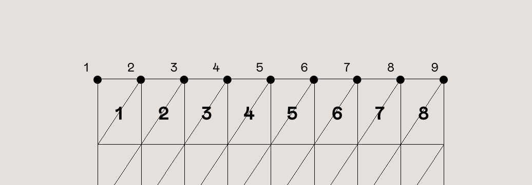
Although it looks the same, Three.js now rendered 100 tubes in the same position. To move them to their respective positions we’ll use an InstancedBufferAttribute.

While a regular BufferAttribute describes the base shape, for example, it’s position, uvs, and normals, an InstanceBufferAttribute describes each instance of the base shape. In our case, each instance is going to have a different aOffset and a different radius/length aMetrics.

When it’s time each instance passes through the vertex shader. WebGL is going to give us the values corresponding to each instance. Then we can position them using those values.

We’ll loop over all the light pairs and calculate their XYZ position:

  1. For the X-axis we’ll calculate the center of its lane. The width of the car, how separated the lights are, and a random offset.
  2. For its Y-axis, we’ll push it up by its radius to make sure it’s on top of the road.
  3. Finally, we’ll give it a random Z-offset based on the length of the road, putting some lights further away than others.

At the end of the loop, we’ll add the offset twice. Once per each light, with only the x-offset as a difference.

class CarLights {
    ...
    init(){
        ...
        let aOffset = [];

            let sectionWidth = options.roadWidth / options.roadSections;

            for (let i = 0; i < options.nPairs; i++) {
              let radius = 1.;
              // 1a. Get it's lane index
              // Instead of random, keep lights per lane consistent
              let section = i % 3;

              // 1b. Get its lane's centered position
              let sectionX =
                section * sectionWidth - options.roadWifth / 2 + sectionWidth / 2;
              let carWidth = 0.5 * sectionWidth;
              let offsetX = 0.5 * Math.random();

              let offsetY = radius * 1.3;

              aOffset.push(sectionX - carWidth / 2 + offsetX);
              aOffset.push(offsetY);
              aOffset.push(-offsetZ);

              aOffset.push(sectionX + carWidth / 2 + offsetX);
              aOffset.push(offsetY);
              aOffset.push(-offsetZ);
            }
        // Add the offset to the instanced geometry.
        instanced.addAttribute(
          "aOffset",
          new THREE.InstancedBufferAttribute(new Float32Array(aOffset), 3, false)
        );
        ...
    }
}

Now that we've added our aOffset attribute, let's go ahead and use it on a vertex shader like a regular bufferAttribute.

We'll replace our MeshBasicMaterial with a shaderMaterial and create a vertex shader where we'll add aOffset to the position:

class TailLights {
	init(){
		...
		const material = new THREE.ShaderMaterial({
			fragmentShader, 
            vertexShader,
            	uniforms: {
                    uColor: new THREE.Uniform(new THREE.Color('0xfafafa'))
                }
		})
		...
	}
}
const fragmentShader = `
uniform vec3 uColor;
  void main() {
      vec3 color = vec3(uColor);
      gl_FragColor = vec4(color,1.);
  }
`;

const vertexShader = `
attribute vec3 aOffset;
  void main() {
		vec3 transformed = position.xyz;

		// Keep them separated to make the next step easier!
	   transformed.z = transformed.z + aOffset.z;
        transformed.xy += aOffset.xy;
	
        vec4 mvPosition = modelViewMatrix * vec4(transformed,1.);
        gl_Position = projectionMatrix * mvPosition;
	}
`;


[https://codesandbox.io/s/infinite-lights-02-road-and-lights-coznb ]

Depending from where you look at the tubes, you'll notice that they might look odd. By default, Three.js' materials don't render the backside of faces side:THREE.FontSide.

While we could fix it by changing it to side: THREE.DoubleSide to render all sides, our tubes are going to be small and fast enough that you won't be able to notice the back faces aren't rendered. We can keep it like that for the sake of performance.

Giving tubes a different length and radius

Creating our tube with a length and radius of 1 was crucial for this section to work. Now we can set the radius and length of each instance only by multiplying on the vertex shader 1 * desiredRadius = desiredRadius.

Let's use the same loop to create a new instancedBufferAttribute called aMetrics. We'll store the length and radius of each instance here.

Remember that wee push to the array twice. One for each of the items in the pair.

class TailLights {
	...
	init(){
	...
	let aMetrics =[];
	for (let i = 0; i < totalLightsPairs; i++) {
     // We give it a minimum value to make sure the lights aren't too thin or short.
     // Give it some randomness but keep it over 0.1
      let radius = Math.random() * 0.1 + 0.1;
     // Give it some randomness but keep it over length *0.02
      let length =
        Math.random() * options.length * 0.08 + options.length * 0.02;
      
      aMetrics.push(radius);
      aMetrics.push(length);

      aMetrics.push(radius);
      aMetrics.push(length);
    }
    instanced.addAttribute(
      "aMetrics",
      new THREE.InstancedBufferAttribute(new Float32Array(aMetrics), 2, false)
    );
    ...
}

Note that we multiplied the position by aMetrics before adding any aOffset. This expands the tubes from their center, and then moves them to their position.

...
const vertexShader = `
attribute vec3 aOffset;
attribute vec2 aMetrics;
  void main() {
    vec3 transformed = position.xyz;

            float radius = aMetrics.r;
            float len = aMetrics.g;

            // 1. Set the radius and length
            transformed.xy *= radius; 
            transformed.z *= len;
		
    // 2. Then move the tubes
   transformed.z = transformed.z + aOffset.z;
   transformed.xy += aOffset.xy;

   vec4 mvPosition = modelViewMatrix * vec4(transformed,1.);
   gl_Position = projectionMatrix * mvPosition;
}
`;

Positioning the lights

We want to have two roads of lights coming from different directions. Let's create the second TailLights and move each to their respective position. To center them both, we'll move them by half the middle island's width and half the road's width.

We'll also give each light its color, and modify the material to use that instead:

class App {
    constructor(){
        this.leftLights  = new TailLights(this, options, 0xff102a);
        this.rightLights = new TailLights(this, options, 0xfafafa);
    }
	init(){
		...
		
        this.leftLights.init();
        this.leftLights.mesh.position.setX(
           -options.roadWidth / 2 - options.islandWidth / 2
        );
        this.rightLights.init();
        this.rightLights.mesh.position.setX(
           options.roadWidth / 2 + options.islandWidth / 2
        );

	}
}
class TailLights {
	constuctor(webgl, options, color){
		this.color = color;
		...
	}
        init(){
            ...
            const material = new THREE.ShaderMaterial({
                fragmentShader, 
                vertexShader,
                    uniforms: {
                        uColor: new THREE.Uniform(new THREE.Color(this.color))
                    }
            })
            ...
        }
}

Looking great! We can already start seeing how the project is coming together!

Moving and looping the lights

Because we created the tube's curve on the z-axis, moving the lights is only a matter of adding and subtracting from the z-axis. We'll use the elapsed time uTime because time is always moving and it's pretty consistent.

Let's begin with adding a uTime uniform and an update method. Then our App class can update the time on both our CarLights. And finally, we'll add time to the z-axis on the vertex shader:

class TailLights {
	init(){
		...
		cosnt material = new THREE.ShaderMaterial({
			fragmentShader, vertexShader,
            	uniforms: {
                    uColor: new THREE.Uniform(new THREE.Color(this.color)),
                    uTime: new THREE.Uniform(0),
                }
		})
		...
	}
        update(t){
            this.mesh.material.uniforms.uTime.value = t;
        }
}
const vertexShader = `
attribute vec3 aOffset;
attribute vec2 aMetrics;
  void main() {
    vec3 transformed = position.xyz;

    float radius = aMetrics.r;
    float len = aMetrics.g;
    transformed.xy *= radius; 
    transformed.z *= len;

            // 1. Add time, and it's position to make it move
            float zOffset = uTime + aOffset.z;
		
            // 2. Then place them in the correct position
            transformed.z += zOffset;

    transformed.xy += aOffset.xy;
	
    vec4 mvPosition = modelViewMatrix * vec4(transformed,1.);
    gl_Position = projectionMatrix * mvPosition;
	}
`;
class App {
  ...
  update(delta) {
    let time = this.clock.elapsedTime;
    this.leftLights.update(time);
    this.rightLights.update(time);
  }
}

It moves ultra-slow, but it moves!

Let's create a new uniform uSpeed and multiply it with uTime to make the animation go faster. Because each road has to go to a different side we'll also add it to the CarLights constructor to make it customizable.

class TailLights {
  constructor(webgl, options, color, speed) {
    ...
    this.speed = speed;
  }
	init(){
		...
		cosnt material = new THREE.ShaderMaterial({
			fragmentShader, vertexShader,
            	uniforms: {
                    uColor: new THREE.Uniform(new THREE.Color(this.color)),
                    uTime: new THREE.Uniform(0),
                    uSpeed: new THREE.Uniform(this.speed)
                }
		})
		...
	}
    ...
}
const vertexShader = `
attribute vec3 aOffset;
attribute vec2 aMetrics;
  void main() {
    vec3 transformed = position.xyz;

    // 1. Set the radius and length
    float radius = aMetrics.r;
    float len = aMetrics.g;
    transformed.xy *= radius; 
    transformed.z *= len;

    // 2. Add time, and it's position to make it move
        	float zOffset = uTime * uSpeed + aOffset.z;
			
    // 2. Then place them in the correct position
    transformed.z += zOffset;

    transformed.xy += aOffset.xy;
	
    vec4 mvPosition = modelViewMatrix * vec4(transformed,1.);
    gl_Position = projectionMatrix * mvPosition;
}
`;

Now that it's fast, let's make it loop.

We'll use the modulo operator mod to find the remainder of z-offset zOffset divided by the total road length uTravelLength. Getting only the remainder makes zOffset loop whenever it goes over uTravelLength.

Then, we'll subtract that from the z-axis and also add the length len to make it loop outside of the camera's view. And that's looping tubes!

Let's go ahead and add the uTravelLength uniform to our material:

class TailLights {
	init(){
		...
		cosnt material = new THREE.ShaderMaterial({
			fragmentShader, vertexShader,
            	uniforms: {
                    uColor: new THREE.Uniform(new THREE.Color(this.color)),
                    uTime: new THREE.Uniform(0),
                    uSpeed: new THREE.Uniform(this.speed)
                    uTime: new THREE.Uniform(0),
                }
		})
		...
	}
}

And let's modify the vertex shaders zOffset to make it loop:

const vertexShader = `
attribute vec3 aOffset;
attribute vec2 aMetrics;
uniform float uTime;
uniform float uSpeed;
uniform float uTravelLength;
  void main() {
    vec3 transformed = position.xyz;
    
    float radius = aMetrics.r;
    float len = aMetrics.g;
    transformed.xy *= radius; 
    transformed.z *= len;

        float zOffset = uTime * uSpeed + aOffset.z;
        // 1. Mod by uTravelLength to make it loop whenever it goes over
        // 2. Add len to make it loop a little bit later
        zOffset = len - mod(zOffset , uTravelLength);

   // Keep them separated to make the next step easier!
   transformed.z = transformed.z +zOffset ;
   transformed.xy += aOffset.xy;

   vec4 mvPosition = modelViewMatrix * vec4(transformed,1.);
   gl_Position = projectionMatrix * mvPosition;
}
`;

If you have a hawk's eye for faulty code, you'll noticed the loop isn't perfect. Behind the camera, the tubes go beyond the road's limits (push the camera back to see it in action). But for our use case, it does the job. Imperfect details outside of the camera don't matter.

Going faster and beyond

When holding left click we want our scene to go Speed Racer mode. Faster, and with a wider camera view.

Because the tube's speed is based on time, we'll add an extra offset to time whenever the left click is down. To make this transition extra smooth, we'll use linear interpolation (lerp) for the speedUp variable.

Note: We keep the timeOffset separate from the actual clock's time. Mutating the clock's time is never a good idea.

function lerp(current, target, speed = 0.1, limit = 0.001) {
  let change = (target - current) * speed;
  if (Math.abs(change) < limit) {
    change = target - current;
  }
  return change;
}

class App {
	constructor(){
		...
		this.speedUpTarget = 0.;
		this.speedUp = 0;
		this.timeOffset = 0;
		this.onMouseDown = this.onMouseDown.bind(this);
		this.onMouseUp = this.onMouseUp.bind(this);
	}
	init(){
		...
        this.container.addEventListener("mousedown", this.onMouseDown);
        this.container.addEventListener("mouseup", this.onMouseUp);
        this.container.addEventListener("mouseout", this.onMouseUp);
	}
  onMouseDown(ev) {
    this.speedUpTarget = 0.1;
  }
  onMouseUp(ev) {
    this.speedUpTarget = 0;
  }
  update(delta){
  	
      // Frame-dependent
    this.speedup += lerp(
      this.speedUp,
      this.speedUpTarget,
        // 10% each frame
      0.1,
      0.00001
    );
      // Also frame-dependent
    this.timeOffset += this.speedUp;
      
      
    let time = this.clock.elapsedTime + this.timeOffset;
    ...
    
  }
}

This is a totally functional and valid animation for our super speed mode; after all, it works. But it'll work differently depending on your Frames Per Second (FPS).

Frame rate independent speed up

The issue with the code above is that every frame we are adding a flat amount to the speed. This animation's speed depends on the frame rate.

It means if your frame rate suddenly becomes lower, or your frame rate was low to begin with, the animation is going to become slower as well. And if your frame rate is higher, the animation is going to speed up.

Resulting in the animations running faster or slower or depending on how many frames per second your computer can achieve, a frame rate dependent animation that takes 2 seconds at 30ps, takes 1 second at 60fps.

Our goal is to animate things using real-time. For all computers, the animations should always take X amount of seconds.

Looking back at our code, we have two animations that are frame rate dependent:

  • the speedUp's linear interpolation by 0.1 each frame
  • adding speedUp to timeOffset each frame

Adding speedUp to timeOffset is a linear process; it only depends on the speedup variable. So, we can make it frame rate independent by multiplying it by how many seconds have passed since the last frame (delta).

This one-line change makes the addition one this.speedUp per second. You might need to bump up the speed since the change makes the addition happen through a whole second.

class App {
	update(delta){
		...
         this.timeOffset += this.speedup * delta;		
		...
	} 
 }

Making the speedUp linear interpolation frame rate independent requires a little bit more math.

In the previous case, adding this.speedUp was a linear process, only dependent on the speedUp value. To make it frame rate independent we used another linear process: multiplying it by delta.

In the case of linear interpolation (lerp), we are trying to move towards the target 10% of the difference each time. This is not a linear process but an exponential process. To make it frame rate independent, we need another exponential process that involves delta.

We'll use the functions found in this article about making lerp frame rate independent.

Instead of moving towards the target 10% each frame, we'll move towards the target based on an exponential function based on time delta instead.

let coefficient = 0.1;
let lerpT = Math.exp(-coefficient * delta); 
this.speedup += lerp(
      this.speedup,
      this.speedupTarget,
      lerpT,
      0.00001
    );

This modification completely changes how our coefficient works. Now, a coefficient of 1.0 moves halfway to the target each second.

If we want to use our old coefficients 0.1 that we know already works fine for 60fps, we can convert the old coefficient into the new ones like this:

let coefficient = -60*Math.log2(1 - 0.1);

Plot twist: Math is actually hard. Although there are some great links out there explaining how all the math makes sense, some of it still flies over my head. If you know more about the theory of why all of this works. Feel free to reach out or type it in the comments. I would love to have a chat!

Repeat the process for the Camera's Field Of View camera.fov. And we also get a frame rate independent animation for the fov. We'll reuse the same lerpT to make it easier.

class App {
	constructor(){
		...
        this.fovTarget = 90;
        ...
	}
  onMouseDown(ev) {
    this.fovTarget = 140;
    ...
  }
  onMouseUp(ev) {
    this.fovTarget = 90;
     ...
  }
  update(delta){
      ...
    let fovChange = lerp(this.camera.fov, this.fovTarget, lerpT );
    if (fovChange !== 0) {
      this.camera.fov += fovChange * delta * 6.;
      this.camera.updateProjectionMatrix();
    }
    ...
    
  }
}

Note: Don't forget to update its transformation matrix after you are done with the changes or it won't update in the GPU.

Modularized distortion

The distortion of each object happens on the vertex shader. And as you can see, all objects share the same distortion. But GLSL doesn't have a module system unless you add something like glslify. If you want to reuse and swap pieces of GLSL code, you have to create that system yourself with JavaScript.

Alternatively, if you have only one or two shaders that need distortion, you can always hard code the distortion GLSL code on each mesh's shader. Then, update each one every time you make a change to the distortion. But try to keep track of updating more than two shaders and you start going insane quickly.

In my case, I chose to keep my sanity and create my own little system. This way I could create multiple distortions and play around with the values for the different demos.

Each distortion is an object with three main properties:

  1. distortion_uniforms: The uniforms this distortion is going to need. Each mesh takes care of adding these into their material.
  2. distortion_chunk: The GLSL code that exposes getDistortion function for the shaders that implement it. getDistortion receives a normalized value progress indicating how far into the road is the point. It returns the distortion of that specific position.
  3. (Optional) getJS: The GLSL code ported to JavaScript. This is useful for creating JS interactions following the curve. Like the camera rotating to face the road as we move along.
const distortion_uniforms = {
  uDistortionX: new THREE.Uniform(new THREE.Vector2(80, 3)),
  uDistortionY: new THREE.Uniform(new THREE.Vector2(-40, 2.5))
};

const distortion_vertex = `
#define PI 3.14159265358979
  uniform vec2 uDistortionX;
  uniform vec2 uDistortionY;

    float nsin(float val){
    return sin(val) * 0.5+0.5;
    }
  vec3 getDistortion(float progress){
        progress = clamp(progress, 0.,1.);
        float xAmp = uDistortionX.r;
        float xFreq = uDistortionX.g;
        float yAmp = uDistortionY.r;
        float yFreq = uDistortionY.g;
        return vec3( 
            xAmp * nsin(progress* PI * xFreq   - PI / 2. ) ,
            yAmp * nsin(progress * PI *yFreq - PI / 2.  ) ,
            0.
        );
    }
`;

const myCustomDistortion = {
    uniforms: distortion_uniforms,
    getDistortion: distortion_vertex,
}

Then, you pass the distortion object as a property in the options given when instantiating the main App class like so:

const myApp = new App(
	container, 
	{
        ... // Bunch of other options
		distortion: myCustomDistortion,
        ...
    }
)
...

From here each object can take the distortion from the options and use it as it needs.

Both, the CarLights and Road classes are going to add distortion.uniforms to their material and modify their shader using Three.js' onBeforeCompile:

const material = new THREE.ShaderMaterial({
	...
	uniforms: Object.assign(
		{...}, // The original uniforms of this object
		options.uniforms
	)
})

material.onBeforeCompile = shader => {
  shader.vertexShader = shader.vertexShader.replace(
    "#include ",
    options.distortion.getDistortion
  );
};

Before Three.js sends our shaders to webGL it checks it's custom GLSL to inject any ShaderChunks your shader needs. onBeforeCompile is a function that happens before Three.js compiles your shader into valid GLSL code. Making it easy to extend any built-in materials.

In our case, we'll use onBeforeCompile to inject our distortion's code. Only to avoid the hassle of injecting it another way.

As it stands now, we aren't injecting any code. We first need to add #include <getDistortion_vertex> to our shaders.

In our CarLights vertex shader we need to map its z-position as its distortion progress. And we'll add the distortion after all other math, right at the end:

// Car Lights Vertex shader
const vertexShader = `
attribute vec3 aOffset;
attribute vec2 aMetrics;
uniform float uTime;
uniform float uSpeed;
uniform float uTravelLength;
#include 
  void main() {
	...
        

		// Map z-position to progress: A range of 0 to 1.
        float progress = abs(transformed.z / uTravelLength);
        transformed.xyz += getDistortion(progress);

	
        vec4 mvPosition = modelViewMatrix * vec4(transformed,1.);
        gl_Position = projectionMatrix * mvPosition;
	}
`;

In our Road class, although we see it flat going towards negative-z because we rotated it, this mesh rotation happens after the vertex shader. In the eyes of our shader, our plane is still vertical y-axis and placed in the center of the scene.

To get the correct distortion, we need to map the y-axis as progress. First, we'll un-center it uTravelLength /2., and then we'll normalize it.

Also, instead of adding the y-distortion to the y-axis, we'll add it to the z-axis instead. Remember, in the vertex shader, the rotation hasn't happened yet.

// Road Vertex shader
const vertexShader = `
uniform float uTravelLength;
#include 
	void main(){
        vec3 transformed = position.xyz;
        
	// Normalize progress to a range of 0 to 1
    float progress = (transformed.y + uTravelLength / 2.) / uTravelLength;
    vec3 distortion  = getDistortion(progress);
    transformed.x += distortion.x;
	// z-axis is becomes the y-axis after mesh rotation. 
    transformed.z += distortion.y;
    gl_Position = projectionMatrix * modelViewMatrix * vec4(transformed.xyz, 1.);
	}
`;

An there you have the final result for this tutorial!

Finishing touches

There are a few ways you can expand and better sell the effect of an infinite road in the middle of the night. Like creating more interesting curves and fading the objects into the background with some fog effect to make the lights seem like they are glowing.

Final Thoughts

I find that re-creating things from outside of the web and simply doing some creative coding, opens me up to a wider range of interesting ideas.

In this tutorial, we learned how to instantiate geometries, create frame rate independent animations and modulized distortions. And we brought it all together to re-create and put some motion into this awesome poster!

Hopefully, you've also liked working through this tutorial! Let me know what you think in the comments and feel free to reach out to me!

High-speed Light Trails in Three.js was written by Daniel Velasquez and published on Codrops.

Real-time Multiside Refraction in Three Steps

When rendering a 3D object you’ll always have to assign it a material to make it visible and to give it a desired appearance, whether it is in some kind of 3D software or in real-time with WebGL.

Many types of materials can be mimicked with out-of-the-box programs in libraries like Three.js, but in this tutorial I will show you how to make objects appear glass-like in three steps using—you guessed it—Three.js.

Step 1: Setup and Front Side Refraction

For this demo I’ll be using a diamond geometry, but you can follow along with a simple box or any other geometry.

Let’s set up our project. We’ll need a renderer, a scene, a perspective camera and our geometry. In order to render our geometry we will need to assign it a material. Creating this material will be the main focus of this tutorial. So go ahead and create a new ShaderMaterial with a basic vertex, and fragment shader.

Contrary to what you’d expect, our material will not be transparent, in fact we will sample and distort anything that’s behind our diamond. To do that we will need to render our scene (without the diamond) to a texture. I’m simply rendering a full screen plane with an orthographic camera, but this could just as well be a scene full of other objects. The easiest way to split the background geometry from the diamond in Three.js is to use Layers.

this.orthoCamera = new THREE.OrthographicCamera( width / - 2,width / 2, height / 2, height / - 2, 1, 1000 );
// assign the camera to layer 1 (layer 0 is default)
this.orthoCamera.layers.set(1);

const tex = await loadTexture('texture.jpg');
this.quad = new THREE.Mesh(new THREE.PlaneBufferGeometry(), new THREE.MeshBasicMaterial({map: tex}));

this.quad.scale.set(width, height, 1);
// also move the plane to layer 1
this.quad.layers.set(1);
this.scene.add(this.quad);

Our render loop will look like this:

this.envFBO = new THREE.WebGLRenderTarget(width, height);

this.renderer.autoClear = false;

render() {
	requestAnimationFrame( this.render );

	this.renderer.clear();

	// render background to fbo
	this.renderer.setRenderTarget(this.envFbo);
	this.renderer.render( this.scene, this.orthoCamera );

	// render background to screen
	this.renderer.setRenderTarget(null);
	this.renderer.render( this.scene, this.orthoCamera );
	this.renderer.clearDepth();

	// render geometry to screen
	this.renderer.render( this.scene, this.camera );
};

Alright, time for a little bit of theory now. Transparent materials like glass are visible because they bend light. That is because light travels slower in glass than it does in air, when a lightwave hits a glass object at an angle, this change in speed causes the wave to change direction. This change in direction of a wave is what describes the phenomenon of refraction.

potential refraction of a light ray

To replicate this in code we will need to know the angle between our eye vector and the surface (normal) vector of our diamond in world space. Let’s update our vertex shader to calculate these vectors.

varying vec3 eyeVector;
varying vec3 worldNormal;

void main() {
	vec4 worldPosition = modelMatrix * vec4( position, 1.0);
	eyeVector = normalize(worldPos.xyz - cameraPosition);
	worldNormal = normalize( modelViewMatrix * vec4(normal, 0.0)).xyz;

	gl_Position = projectionMatrix * modelViewMatrix * vec4(position, 1.0);
}

In our fragment shader we can now use eyeVector and worldNormal as the first two parameters of glsl’s built-in refract function. The third parameter is the ratio of indices of refraction, meaning the index of refraction (IOR) of our fast medium—air—divided by the IOR of our slow medium—glass. In this case that will be 1.0/1.5, but you can tweak this value to achieve your desired result. For example the IOR of water is 1.33 and diamond has an IOR of 2.42.

uniform sampler2D envMap;
uniform vec2 resolution;

varying vec3 worldNormal;
varying vec3 viewDirection;

void main() {
	// get screen coordinates
	vec2 uv = gl_FragCoord.xy / resolution;

	vec3 normal = worldNormal;
	// calculate refraction and add to the screen coordinates
	vec3 refracted = refract(eyeVector, normal, 1.0/ior);
	uv += refracted.xy;
	
	// sample the background texture
	vec4 tex = texture2D(envMap, uv);

	vec4 output = tex;
	gl_FragColor = vec4(output.rgb, 1.0);
}

Nice! We successfully wrote a refraction shader. But our diamond is hardly visible… That is partly because we’ve only handled one visual property of glass. Not all light will pass through the material to be refracted, in fact, part of it will be reflected. Let’s see how we can implement that!

Step 2: Reflection and the Fresnel equation

For the sake of simplicity, in this tutorial we are not going to calculate proper reflections but just use a white color for our reflected light. Now, how do we know when to reflect and when to refract? In theory this depends on the refractive index of the material, when the angle between the incident vector and the surface normal is greater than the critical angle, the light wave will be reflected.

fresnel-diagram

In our fragment shader we will use the Fresnel equation to calculate the ratio between reflected and refracted rays. Unfortunately, glsl does not have this equation built-in as well, but you can just copy it from here:

float Fresnel(vec3 eyeVector, vec3 worldNormal) {
	return pow( 1.0 + dot( eyeVector, worldNormal), 3.0 );
}

We can now simply mix the refracted texture color with our white reflection color based on the Fresnel ratio we just calculated.

uniform sampler2D envMap;
uniform vec2 resolution;

varying vec3 worldNormal;
varying vec3 viewDirection;

float Fresnel(vec3 eyeVector, vec3 worldNormal) {
	return pow( 1.0 + dot( eyeVector, worldNormal), 3.0 );
}

void main() {
	// get screen coordinates
	vec2 uv = gl_FragCoord.xy / resolution;

	vec3 normal = worldNormal;
	// calculate refraction and add to the screen coordinates
	vec3 refracted = refract(eyeVector, normal, 1.0/ior);
	uv += refracted.xy;

	// sample the background texture
	vec4 tex = texture2D(envMap, uv);

	vec4 output = tex;

	// calculate the Fresnel ratio
	float f = Fresnel(eyeVector, normal);

	// mix the refraction color and reflection color
	output.rgb = mix(output.rgb, vec3(1.0), f);

	gl_FragColor = vec4(output.rgb, 1.0);
}

That’s already looking a lot better, but there’s still something off about it… Ah right, we can’t see the other side of transparent object. Let’s fix that!

Step 3: Multiside refraction

With the things we’ve learned so far about reflections and refractions we can understand that light can bounce back and forth a couple times inside the object before exiting it.

To achieve a physically correct result we will have to trace each ray, but unfortunately this computation is way too heavy to render in real-time. So instead, I will show you a simple approximation to at least visualize the back faces of our diamond.

We’ll need the world normals of our geometry’s front and back faces in one fragment shader. Since we cannot render both sides at the same time we’ll need to render the back face normals to a texture first.

normals

Let’s make a new ShaderMaterial like we did in step 1, but this time we will render the world normals to gl_FragColor.

varying vec3 worldNormal;

void main() {
	gl_FragColor = vec4(worldNormal, 1.0);
}

Next we’ll update our render loop to include the back face pass.

this.backfaceFbo = new THREE.WebGLRenderTarget(width, height);

...

render() {
	requestAnimationFrame( this.render );

	this.renderer.clear();

	// render background to fbo
	this.renderer.setRenderTarget(this.envFbo);
	this.renderer.render( this.scene, this.orthoCamera );

	// render diamond back faces to fbo
	this.mesh.material = this.backfaceMaterial;
	this.renderer.setRenderTarget(this.backfaceFbo);
	this.renderer.clearDepth();
	this.renderer.render( this.scene, this.camera );

	// render background to screen
	this.renderer.setRenderTarget(null);
	this.renderer.render( this.scene, this.orthoCamera );
	this.renderer.clearDepth();

	// render diamond with refraction material to screen
	this.mesh.material = this.refractionMaterial;
	this.renderer.render( this.scene, this.camera );
};

Now we sample the back face normal texture in our refraction material.

vec3 backfaceNormal = texture2D(backfaceMap, uv).rgb;

And finally we combine the front and back face normals.

float a = 0.33;
vec3 normal = worldNormal * (1.0 - a) - backfaceNormal * a;

In this equation, a is simply a scalar value indicating how much of the back face’s normal should be applied.

We did it! We can see all sides of our diamond, only because of the refractions and reflections we have applied to its material.

Limitations

As I already explained, it is not quite possible to render physically correct transparent materials in real-time with this method. Another problem occurs when rendering multiple glass objects in front of each other. Since we only sample the environment once we won’t be able to see through a chain of objects. And lastly, a screen space refraction like I demoed here won’t work very well near the edges of the canvas since rays may refract to values outside of its boundaries and we didn’t capture that data when rendering the background scene to the render target.

Of course, there are ways to overcome these limitations, but they might not all be great solutions for your real-time rendering in WebGL.

I hope you enjoyed following along with this demo and you have learned something from it. I’m curious to see what you can do with it! Let me know on Twitter. Also don’t hesitate to ask me anything!

Real-time Multiside Refraction in Three Steps was written by Jesper Vos and published on Codrops.

Making Gooey Image Hover Effects with Three.js

Flash’s grandson, WebGL has become more and more popular over the last few years with libraries like Three.js, PIXI.js or the recent OGL.js. Those are very useful for easily creating a blank board where the only boundaries are your imagination. We see more and more, often subtle integration of WebGL in an interface for hover, scroll or reveal effects. Examples are the gallery of articles on Hello Monday or the effects seen on cobosrl.co.

In this tutorial, we’ll use Three.js to create a special gooey texture that we’ll use to reveal another image when hovering one. Head over to the demo to see the effect in action. For the demo itself, I’ve created a more practical example that shows a vertical scrollable layout with images, where each one has a variation of the effect. You can click on an image and it will expand to a larger version while some other content shows up (just a mock-up). We’ll go over the most interesting parts of the effect, so that you get an understanding of how it works and how to create your own.

I’ll assume that you are comfortable with JavaScript and have some knowledge of Three.js and shader logic. If you’re not, have a look at the Three.js documentation or The Book of Shaders, Three.js Fundamentals or Discover Three.js.

Attention: This tutorial covers many parts; if you prefer, you can skip the HTML/CSS/JavaScript part and go directly go to the shaders section.

Now that we are clear, let’s do this!

Create the scene in the DOM

Before we start making some magic, we are first going to mark up the images in the HTML. It will be easier to handle resizing our scene after we’ve set up the initial position and dimension in HTML/CSS rather than positioning everything in JavaScript. Moreover, the styling part should be only made with CSS, not JavaScript. For example, if our image has a ratio of 16:9 on desktop but a 4:3 ratio on mobile, we just want to handle this using CSS. JavaScript will only get the new values and do its stuff.

// index.html

<section class="container">
	<article class="tile">
		<figure class="tile__figure">
			<img data-src="path/to/my/image.jpg" data-hover="path/to/my/hover-image.jpg" class="tile__image" alt="My image" width="400" height="300" />
		</figure>
	</article>
</section>

<canvas id="stage"></canvas>
// style.css

.container {
	display: flex;
	align-items: center;
	justify-content: center;
	width: 100%;
	height: 100vh;
	z-index: 10;
}

.tile {
	width: 35vw;
	flex: 0 0 auto;
}

.tile__image {
	width: 100%;
	height: 100%;
	object-fit: cover;
	object-position: center;
}

canvas {
	position: fixed;
	left: 0;
	top: 0;
	width: 100%;
	height: 100vh;
	z-index: 9;
}

As you can see above, we have create a single image that is centered in the middle of our screen. Did you notice the data-src and data-hover attributes on the image? These will be our reference images and we’ll load both of these later in our script with lazy loading.

Don’t forget the canvas. We’ll stack it below our main section to draw the images in the exact same place as we have placed them before.

Create the scene in JavaScript

Let’s get started with the less-easy-but-ok part! First, we’ll create the scene, the lights, and the renderer.

// Scene.js

import * as THREE from 'three'

export default class Scene {
	constructor() {
		this.container = document.getElementById('stage')

		this.scene = new THREE.Scene()
		this.renderer = new THREE.WebGLRenderer({
			canvas: this.container,
			alpha: true,
	  })

		this.renderer.setSize(window.innerWidth, window.innerHeight)
		this.renderer.setPixelRatio(window.devicePixelRatio)

		this.initLights()
	}

	initLights() {
		const ambientlight = new THREE.AmbientLight(0xffffff, 2)
		this.scene.add(ambientlight)
	}
}

This is a very basic scene. But we need one more essential thing in our scene: the camera. We have a choice between two types of cameras: orthographic or perspective. If we keep our image flat, we can use the first one. But for our rotation effect, we want some perspective as we move the mouse around.

In Three.js (and other libraries for WebGL) with a perspective camera, 10 unit values on our screen are not 10px. So the trick here is to use some math to transform 1 unit to 1 pixel and change the perspective to increase or decrease the distortion effect.

// Scene.js

const perspective = 800

constructor() {
	// ...
	this.initCamera()
}

initCamera() {
	const fov = (180 * (2 * Math.atan(window.innerHeight / 2 / perspective))) / Math.PI

	this.camera = new THREE.PerspectiveCamera(fov, window.innerWidth / window.innerHeight, 1, 1000)
	this.camera.position.set(0, 0, perspective)
}

We’ll set the perspective to 800 to have a not-so-strong distortion as we rotate the plane. The more we increase the perspective, the less we’ll perceive the distortion, and vice versa.

The last thing we need to do is to render our scene in each frame.

// Scene.js

constructor() {
	// ...
	this.update()
}

update() {
	requestAnimationFrame(this.update.bind(this))
	
	this.renderer.render(this.scene, this.camera)
}

If your screen is not black, you are on the right way!

Build the plane with the correct sizes

As we mentioned above, we have to retrieve some additional information from the image in the DOM like its dimension and position on the page.

// Scene.js

import Figure from './Figure'

constructor() {
	// ...
	this.figure = new Figure(this.scene)
}
// Figure.js

export default class Figure {
	constructor(scene) {
		this.$image = document.querySelector('.tile__image')
		this.scene = scene

		this.loader = new THREE.TextureLoader()

		this.image = this.loader.load(this.$image.dataset.src)
		this.hoverImage = this.loader.load(this.$image.dataset.hover)
		this.sizes = new THREE.Vector2(0, 0)
		this.offset = new THREE.Vector2(0, 0)

		this.getSizes()

		this.createMesh()
	}
}

First, we create another class where we pass the scene as a property. We set two new vectors, dimension and offset, in which we’ll store the dimension and position of our DOM image.

Furthermore, we’ll use a TextureLoader to “load” our images and convert them into a texture. We need to do that as we want to use these pictures in our shaders.

We need to create a method in our class to handle the loading of our images and wait for a callback. We could achieve that with an async function but for this tutorial, let’s keep it simple. Just keep in mind that you’ll probably need to refactor this a bit for your own purposes.

// Figure.js

// ...
	getSizes() {
		const { width, height, top, left } = this.$image.getBoundingClientRect()

		this.sizes.set(width, height)
		this.offset.set(left - window.innerWidth / 2 + width / 2, -top + window.innerHeight / 2 - height / 2)
	}
// ...

We get our image information in the getBoundingClientRect object. After that, we’ll pass these to our two variables. The offset is here to calculate the distance between the center of the screen and the object on the page.

// Figure.js

// ...
	createMesh() {
		this.geometry = new THREE.PlaneBufferGeometry(1, 1, 1, 1)
		this.material = new THREE.MeshBasicMaterial({
			map: this.image
		})

		this.mesh = new THREE.Mesh(this.geometry, this.material)

		this.mesh.position.set(this.offset.x, this.offset.y, 0)
		this.mesh.scale.set(this.sizes.x, this.sizes.y, 1)

		this.scene.add(this.mesh)
	}
// ...

After that, we’ll set our values on the plane we’re building. As you can notice, we have created a plane of 1 on 1px with 1 row and 1 column. As we don’t want to distort the plane, we don’t need a lot of faces or vertices. So let’s keep it simple.

But why scale it while we can set the size directly? Glad you asked.

Because of the resizing part. If we want to change the size of our mesh afterwards, there is no other proper way than this one. While it’s easier to change the scale of the mesh, it’s not for the dimension.

For the moment, we set a MeshBasicMaterial, just to see if everything is fine.

Get mouse coordinates

Now that we have built our scene with our mesh, we want to get our mouse coordinates and, to keep things easy, we’ll normalize them. Why normalize? Because of the coordinate system in shaders.

coordinate-system

As you can see in the figure above, we have normalized the values for both of our shaders. So to keep things simple, we’ll prepare our mouse coordinate to match the vertex shader coordinate.

If you’re lost at this point, I recommend you to read the Book of Shaders and the respective part of Three.js Fundamentals. Both have good advice and a lot of examples to help understand what’s going on.

// Figure.js

// ...

this.mouse = new THREE.Vector2(0, 0)
window.addEventListener('mousemove', (ev) => { this.onMouseMove(ev) })

// ...

onMouseMove(event) {
	TweenMax.to(this.mouse, 0.5, {
		x: (event.clientX / window.innerWidth) * 2 - 1,
		y: -(event.clientY / window.innerHeight) * 2 + 1,
	})

	TweenMax.to(this.mesh.rotation, 0.5, {
		x: -this.mouse.y * 0.3,
		y: this.mouse.x * (Math.PI / 6)
	})
}

For the tween parts, I’m going to use TweenMax from GreenSock. This is the best library ever. EVER. And it’s perfect for our purpose. We don’t need to handle the transition between two states, TweenMax will do it for us. Each time we move our mouse, TweenMax will update the position and the rotation smoothly.

One last thing before we continue: we’ll update our material from MeshBasicMaterial to ShaderMaterial and pass some values (uniforms) and shaders.

// Figure.js

// ...

this.uniforms = {
	u_image: { type: 't', value: this.image },
	u_imagehover: { type: 't', value: this.hover },
	u_mouse: { value: this.mouse },
	u_time: { value: 0 },
	u_res: { value: new THREE.Vector2(window.innerWidth, window.innerHeight) }
}

this.material = new THREE.ShaderMaterial({
	uniforms: this.uniforms,
	vertexShader: vertexShader,
	fragmentShader: fragmentShader
})

update() {
	this.uniforms.u_time.value += 0.01
}

We passed our two textures, the mouse position, the size of our screen and a variable called u_time which we will increment each frame.

But keep in mind that it’s not the best way to do that. For example, we only need to increment when we are hovering the figure, not every frame. I’m not going into details, but performance-wise, it’s better to just update our shader only when we need it.

The logic behind the trick & how to use noise

Still here? Nice! Time for some magic tricks.

I will not explain what noise is and where it comes from. If you’re interested, be sure to read this page from The Book of Shaders. It’s well explained.

Long story short, Noise is a function that gives us a value between -1 and 1 based on values we pass through. It will output a random pattern but more organic.

Thanks to noise, we can generate a lot of different shapes, like maps, random patterns, etc.

noise-example1

noise-example2

Let’s start with a 2D noise result. Just by passing the coordinate of our texture, we’ll have something like a cloud texture.

noise-result1

But there are several kinds of noise functions. Let’s use a 3D noise by giving one more parameter like … the time? The noise pattern will evolve and change over time. By changing the frequency and the amplitude, we can give some movement and increase the contrast.

It will be our first base.

noise-result2

Second, we’ll create a circle. It’s quite easy to build a simple shape like a circle in the fragment shader. We just take the function from The Book of Shaders: Shapes to create a blurred circle, increase the contrast and voilà!

noise-result3

Last, we add these two together, play with some variables, cut a “slice” of this and tadaaa:

noise-result4

We finally mix our textures together based on this result and here we are, easy peasy lemon squeezy!

Let’s dive into the code.

Shaders

We won’t really need the vertex shader here so this is our code:

 // vertexShader.glsl
varying vec2 v_uv;

void main() {
	v_uv = uv;

	gl_Position = projectionMatrix * modelViewMatrix * vec4(position, 1.0);
}

ShaderMaterial from Three.js provides some useful default variables when you’re a beginner:

  • position (vec3): the coordinates of each vertex of our mesh
  • uv (vec2): the coordinates of our texture
  • normals (vec3): normal of each vertex our mesh have.

Here we’re just passing the UV coordinates from the vertex shader to fragment shader.

Create the circle

Let’s use the function from The Book of Shaders to build our circle and add a variable to handle the blurriness of our edges.

Moreover, we’ll add the mouse position to the origin of our circle. This way, the circle will be moving as long as we move our mouse over our image.

// fragmentShader.glsl
uniform vec2 u_mouse;
uniform vec2 u_res;

float circle(in vec2 _st, in float _radius, in float blurriness){
	vec2 dist = _st;
	return 1.-smoothstep(_radius-(_radius*blurriness), _radius+(_radius*blurriness), dot(dist,dist)*4.0);
}

void main() {
	vec2 st = gl_FragCoord.xy / u_res.xy - vec2(1.);
	// tip: use the following formula to keep the good ratio of your coordinates
	st.y *= u_res.y / u_res.x;

	vec2 mouse = u_mouse;
	// tip2: do the same for your mouse
	mouse.y *= u_res.y / u_res.x;
	mouse *= -1.;
	
	vec2 circlePos = st + mouse;
	float c = circle(circlePos, .03, 2.);

	gl_FragColor = vec4(vec3(c), 1.);
}

Make some noooooise

As we saw above, the noise function has several parameters and gives us a smooth cloudy pattern. How could we have that? Glad you asked.

For this part, I’m using glslify and glsl-noise, and two npm packages to include other functions. It keeps our shader a little bit more readable and avoids having a lot of displayed functions that we will not use after all.

// fragmentShader.glsl
#pragma glslify: snoise2 = require('glsl-noise/simplex/2d')

//...

varying vec2 v_uv;

uniform float u_time;

void main() {
	// ...

	float n = snoise2(vec2(v_uv.x, v_uv.y));

	gl_FragColor = vec4(vec3(n), 1.);
}

noise-result5

By changing the amplitude and the frequency of our noise (exactly like the sin/cos functions), we can change the render.

// fragmentShader.glsl

float offx = v_uv.x + sin(v_uv.y + u_time * .1);
float offy = v_uv.y - u_time * 0.1 - cos(u_time * .001) * .01;

float n = snoise2(vec2(offx, offy) * 5.) * 1.;

noise-result6

But it isn’t evolving through time! It is distorted but that’s it. We want more. So we will use noise3d instead and pass a 3rd parameter: the time.

float n = snoise3(vec3(offx, offy, u_time * .1) * 4.) * .5;

As you can see, I changed the amplitude and the frequency to have the render I desire.

Alright, let’s add them together!

Merging both textures

By just adding these together, we’ll already see an interesting shape changing through time.

noise-result7

To explain what’s happening, let’s imagine our noise is like a sea floating between -1 and 1. But our screen can’t display negative color or pixels more than 1 (pure white) so we are just seeing the values between 0 and 1.

explanation-noise1

And our circle is like a flan.

explanation-noise2

By adding these two shapes together it will give this very approximative result:

explanation-noise3

Our very white pixels are only pixels outside the visible spectrum.

If we scale down our noise and subtract a small number, it will be completely moving down your waves until it disappears above the surface of the ocean of visible colors.

noise-result8

float n = snoise(vec3(offx, offy, u_time * .1) * 4.) - 1.;

Our circle is still there but not enough visible to be displayed. If we multiply its value, it will be more contrasted.

float c = circle(circlePos, 0.3, 0.3) * 2.5;

noise-result9

We are almost there! But as you can see, there are still some details missing. And our edges aren’t sharp at all.

To avoid that, we’ll use the built-in smoothstep function.

float finalMask = smoothstep(0.4, 0.5, n + c);

gl_FragColor = vec4(vec3(finalMask), 1.);

Thanks to this function, we’ll cut a slice of our pattern between 0.4 et 0.5, for example. The shorter the space is between these values, the sharper the edges are.

Finally, we can mix our two textures to use them as a mask.

uniform sampler2D u_image;
uniform sampler2D u_imagehover;

// ...

vec4 image = texture2D(u_image, uv);
vec4 hover = texture2D(u_imagehover, uv);

vec4 finalImage = mix(image, hover, finalMask);

gl_FragColor = finalImage;

We can change a few variables to have a more gooey effect:

// ...

float c = circle(circlePos, 0.3, 2.) * 2.5;

float n = snoise3(vec3(offx, offy, u_time * .1) * 8.) - 1.;

float finalMask = smoothstep(0.4, 0.5, n + pow(c, 2.));

// ...

And voilà!

Check out the full source here or take a look at the live demo.

Mic drop

Congratulations to those who came this far. I haven’t planned to explain this much. This isn’t perfect and I might have missed some details but I hope you’ve enjoyed this tutorial anyway. Don’t hesitate to play with variables, try other noise functions and try to implement other effects using the mouse direction or play with the scroll!

If you have any questions, let me know in the comments section! I also encourage you to download the demo, it’s a little bit more complex and shows the effects in action with hover and click effects ¯\_(?)_/¯

References and Credits

Making Gooey Image Hover Effects with Three.js was written by Arno Di Nunzio and published on Codrops.